Step up Step down Chopper or Buck Boost Converter – Working Principle:
A chopper can also be used for stepping up or down the supply voltage by varying its duty cycle. This is also known as a buck-boost converter. The principle of operation is illustrated in Fig. 27.29. As shown, the output voltage polarity is opposite to that of input voltage V.
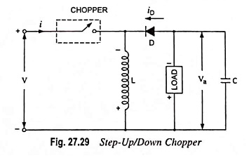
When the chopper is on, the supply current flows through the path V+ – chopper – inductor L – V–. As a result energy is stored in the inductor. When the chopper is made off, the current through the inductor L decreases. As a result an emf is induced in the inductor with lower end positive and the energy stored in the inductor is released through the load and diode and the voltage across the load is negative as illustrated. It is thus used to reverse the polarity of load voltage w.r.t. source voltage.
The energy stored in inductor L during on-period Ton is given by
![]()
But the average current through the inductor, as in case of step-up chopper discussed in previous topic is

During off period Toff, the energy released by inductor to the load is

Under steady-state condition, assuming no loss of power.
Energy stored in inductor = Energy released to load
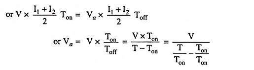
Substituting Ton/T = α in above equation, we have

Equation (27.47) can be used for step-up and step-down operation of chopper. In the range 0 < α < 0.5 the circuit operates in step-down mode while for duty cycle in the range 0.5 < α < 1 it acts as a step-up chopper.