Base Modulation Circuit Working Principle
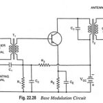
Base Modulation Circuit Working Principle: The circuit for base modulation is shown in Fig. 22.28. The carrier signal from a crystal oscillator is coupled to the base terminal of the…
Collector Modulation Circuit - Working, Advantages and Disadvantages: This is very popular method for AM generation. The circuit diagram for collector modulation is shown in Fig. 22.26. Here, the transistor…
Block Diagram of AM Transmitter: Block Diagram of AM Transmitter is shown in Fig. 22.25. Sound waves produced by speech or music strike the diaphragm of a microphone that converts…
Output Stage of an Op Amp and its Voltage Transfer Characteristics: The output stage of an op amp is another requirement which should have very small output impedance and provide…
Voltage Level Translator (Level Shifter): Voltage Level Translator (Level Shifter) is usually an emitter follower circuit which is used to shift the dc level at the output of the intermediate…
Feedback Pair Connection - Operation and its Equivalent Circuit: The feedback pair connection (Fig. 19.58) is a two-transistor circuit that operates like the Darlington amplifier. It makes use of a…
Emitter Follower Circuit - Operation, Advantages and Applications: Emitter Follower Circuit is also a negative current feedback circuit. This circuits exhibits a large input impedance, a small output impedance, and…
Effect of Negative Feedback on Output Impedance: Just as high input impedance is advantageous to an amplifier, so is low output impedance. With lower output impedance, the amplifier is better…