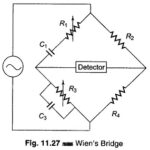
Wien Bridge Circuit Diagram
Wien Bridge Circuit Diagram: The Wien Bridge Circuit Diagram shown in Fig. 11.27 has a series RC combination in one arm and a parallel combination in the adjoining arm. Wien's…
Continue Reading
Wien Bridge Circuit Diagram