Oil Circuit Breaker Diagram:
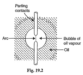
In such Oil Circuit Breaker Diagram, some insulating oil (e.g., transformer oil) is used as an arc quenching medium. The contacts are opened under oil and an arc is struck between them. The heat of the arc evaporates the surrounding oil and dissociates it into a substantial volume of gaseous hydrogen at high pressure. The hydrogen gas occupies a volume about one thousand times that of the oil decomposed. The oil is, therefore, pushed away from the arc and an expanding hydrogen gas bubble surrounds the arc region and adjacent portions of the contacts (See Fig. 19.2). The arc extinction is facilitated mainly by two processes. Firstly, the hydrogen gas has high heat conductivity and cools the arc, thus aiding the de-ionisation of the medium between the contacts. Secondly, the gas sets up turbulence in the oil and forces it into the space between contacts, thus eliminating the arcing products from the arc path. The result is that arc is extinguished and circuit current interrupted.
The advantages of oil as an arc quenching medium are :
- It absorbs the arc energy to decompose the oil into gases which have excellent cooling properties.
- It acts as an insulator and permits smaller clearance between live conductors and earthed components.
- The surrounding oil presents cooling surface in close proximity to the arc.
The disadvantages of oil as an arc quenching medium are :
- It is inflammable and there is a risk of a fire.
- It may form an explosive mixture with air
- The arcing products (e.g., carbon) remain in the oil and its quality deteriorates with successive operations. This necessitates periodic checking and replacement of oil.
Types of Oil Circuit Breaker:
The Oil Circuit Breaker Diagram find extensive use in the power system. These can be classified into the following types :
1. Bulk Oil Circuit Breaker:
which use a large quantity of oil. The oil has to serve two purposes. Firstly, it extinguishes the arc during opening of contacts and secondly, it insulates the current conducting parts from one another and from the earthed tank. Such circuit breakers may be classified into :
- Plain Break Oil Circuit Breaker
- Arc Control Oil Circuit Breaker
In the former type, no special means is available for controlling the arc and the contacts are directly exposed to the whole of the oil in the tank. However, in the latter type, special arc control devices are employed to get the beneficial action of the arc as efficiently as possible.
2. Low Oil Circuit Breaker which use minimum amount of oil. In such circuit breakers, oil is used only for arc extinction; the current conducting parts are insulated by air or porcelain or organic insulating material.
Plain Break Oil Circuit Breakers:
A plain-break oil circuit breaker involves the simple process of separating the contacts under the whole of the oil in the tank. There is no special system for arc control other than the increase in length caused by the separation of contacts. The arc extinction occurs when a certain critical gap between the contacts is reached.
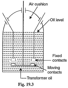
The plain-break oil circuit breaker is the earliest type from which all other circuit breakers have developed. It has a very simple construction. It consists of fixed and moving contacts enclosed in a strong weather-tight earthed tank containing oil upto a certain level and an air cushion above the oil level. The air cushion provides sufficient room to allow for the reception of the arc gases without the generation of unsafe pressure in the dome of the circuit breaker. It also absorbs the mechanical shock of the upward oil movement. Fig. 19.3 shows a double break plain Oil Circuit Breaker Diagram. It is called a double break because it provides two breaks in series.
Under normal operating conditions, the fixed and moving contacts remain closed and the breaker carries the normal circuit current. When a fault occurs, the moving contacts are pulled down by the protective system and an arc is struck which vapourises the oil mainly into hydrogen gas. The arc extinction is facilitated by the following processes :
- The hydrogen gas bubble generated around the arc cools the arc column and aids the de-ionisation of the medium between the contacts.
- The gas sets up turbulence in the oil and helps in eliminating the arcing products from the arc path.
- As the arc lengthens due to the separating contacts, the dielectric strength of the medium is increased.
The result of these actions is that at some critical gap length, the arc is extinguished and the circuit current is interrupted.
Disadvantages
- There is no special control over the arc other than the increase in length by separating the moving contacts. Therefore, for successful interruption, long arc length is necessary.
- These breakers have long and inconsistent arcing times:
- These breakers do not permit high speed interruption.
Due to these disadvantages, plain-break oil circuit breakers are used only for low-voltage applications where high breaking-capacities are not important. It is a usual practice to use such breakers for low capacity installations for voltages not exceeding 11 kV.
Arc Control Oil Circuit Breakers:
In case of plain break Oil Circuit Breaker Diagram discussed above, there is very little artificial control over the arc. Therefore, comparatively long arc length is essential in order that turbulence in the oil caused by the gas may assist in quenching it. However, it is necessary and desirable that final arc extinction should occur while the contact gap is still short. For this purpose, some arc control is incorporated and the breakers are then called arc control circuit breakers. There are two types of such breakers, namely :
- Self Blast Oil Circuit Breaker— in which arc control is provided by internal means i.e. the arc itself is employed for its own extinction efficiently.
- Forced Blast Oil Circuit Breaker— in which arc control is provided by mechanical means external to the circuit breaker.
1. Self Blast Oil Circuit Breaker: In this type of circuit breaker, the gases produced during arcing are confined to a small volume by the use of an insulating rigid pressure chamber or pot surrounding the contacts. Since the space available for the arc gases is restricted by the chamber, a very high pressure is developed to force the oil and gas through or around the arc to extinguish it. The magnitude of pressure developed depends upon the value of fault current to be interrupted. As the pressure is generated by the arc itself, therefore, such breakers are sometimes called self-generated pressure oil circuit breakers.
The pressure chamber is relatively cheap to make and gives reduced final arc extinction gap length and arcing time as against the plain-break oil circuit breaker. Several designs of pressure chambers (sometimes called explosion pots) have been developed and a few of them are described below :
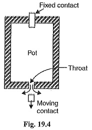
(a) Plain explosion pot: It is a rigid cylinder of insulating material and encloses the fixed and moving contacts (See Fig. 19.4). The moving contact is a cylindrical rod passing through a restricted opening (called throat) at the bottom. When a fault occurs, the contacts get separated and an arc is struck between them. The heat of the arc decomposes oil into a gas at very high pressure in the pot. This high pressure forces the oil and gas through and round the arc to extinguish it. If the final arc extinction does not take place while the moving contact is still within the pot, it occurs immediately after the moving contact leaves the pot. It is because emergence of the moving contact from the pot is followed by a violent rush of gas and oil through the throat producing rapid extinction.
The principal limitation of this type of pot is that it cannot be used for very low or for very high fault currents. With low fault currents, the pressure developed is small, thereby increasing the arcing time. On the other hand, with high fault currents, the gas is produced so rapidly that explosion pot is liable to burst due to high pressure. For this reason, plain explosion pot operates well on moderate short-circuit currents only where the rate of gas evolution is moderate.
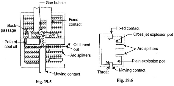
(b) Cross jet explosion pot: This type of pot is just a modification of plain explosion pot and is illustrated in Fig. 19.5. It is made of insulating material and has channels on one side which act as arc splitters. The arc splitters help in increasing the arc length, thus facilitating arc extinction. When a fault occurs, the moving contact of the circuit breaker begins to separate. As the moving contact is withdrawn, the arc is initially struck in the top of the pot. The gas generated by the arc exerts pressure on the oil in the back passage. When the moving contact uncovers the arc splitter ducts, fresh oil is forced across the arc path. The arc is, therefore, driven sideways into the “arc splitters” which increase the arc length, causing arc extinction.
The cross-jet explosion pot is quite efficient for interrupting heavy fault currents. However, for low fault currents, the gas pressure is small and consequently the pot does not give a satisfactory operation.
(c) Self-compensated explosion pot: This type of pot is essentially a combination of plain explosion pot and cross jet explosion pot. Therefore, it can interrupt low as well as heavy short circuit currents with reasonable accuracy.
Fig. 19.6 shows the schematic diagram of self-compensated explosion pot. It consists of two chambers, the upper chamber is the cross-jet explosion pot with two arc splitter ducts while the lower one is the plain explosion pot. When the short-circuit current is heavy, the rate of generation of gas is very high and the device behaves as a cross-jet explosion pot. The arc extinction takes place when the moving contact uncovers the first or second arc splitter duct. However, on low short-circuit currents, the rate of gas generation is small and the tip of the moving contact has the time to reach the lower chamber. During this time, the gas builds up sufficient pressure as there is very little leakage through arc splitter ducts due to the obstruction offered by the arc path and right angle bends. When the moving contact comes out of the throat, the arc is extinguished by plain pot action.
It may be noted that as the severity of the short-circuit current increases, the device operates less and less as a plain explosion pot and more and more as a cross-jet explosion pot. Thus the tendency is to make the control self-compensating over the full range of fault currents to be interrupted.
2. Forced Blast Oil Circuit Breaker: In the self-blast Oil Circuit Breaker Diagram discussed above, the arc itself generates the necessary pressure to force the oil across the arc path. The major limitation of such breakers is that arcing times tend to be long and inconsistent when operating against currents considerably less than the rated currents. It is because the gas generated is much reduced at low values of fault currents. This difficulty is overcome in forced-blast oil circuit breakers in which the necessary pressure is generated by external mechanical means independent of the fault currents to be broken.
In a forced -blast Oil Circuit Breaker Diagram; oil pressure is created by the piston-cylinder arrangement. The movement of the piston is mechanically coupled to the moving contact. When a fault occurs, the contacts get separated by the protective system and an arc is struck between the contacts. The piston forces a jet of oil towards the contact gap to extinguish the arc. It may be noted that necessary oil pressure produced does not in any way depend upon the fault current to be broken.
Advantages
- Since oil pressure developed is independent of the fault current to be interrupted, the performance at low currents is more consistent than with self-blast oil circuit breakers.
- The quantity of oil required is reduced considerably.
Low Oil Circuit Breaker:
In the bulk oil circuit breakers discussed so far, the oil has to perform two functions. Firstly, it acts as an arc quenching medium and secondly, it insulates the live parts from earth. It has been found that only a small percentage of oil is actually used for arc extinction while the major part is utilized for insulation purposes. For this reason, the quantity of oil in bulk oil circuit breakers reaches a very high figure as the system voltage increases. This not only increases the expenses tank size and weight of the breaker but it also increases the fire risk and maintenance problems.
The fact that only a small percentage of oil (about 10% of total) in the bulk oil circuit breaker is actually used for arc extinction leads to the question as to why the remainder of the oil, that is not immediately surrounding the device, should not be omitted with consequent saving in bulk, weight and fire risk. This led to the development of low-oil circuit breaker. A low oil Oil Circuit Breaker Diagram employs solid materials for insulation purposes and uses a small quantity of oil which is just sufficient for arc extinction. As regards quenching the arc, the oil behaves identically in bulk as well as low oil circuit breaker. By using suitable arc control devices, the arc extinction can be further facilitated in a low oil circuit breaker.
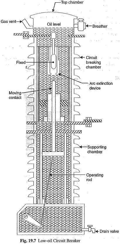
Construction: Fig 19.7 shows the cross section of a single phase Oil Circuit Breaker Diagram. There are two compartments separated from each other but both filled with oil. The upper chamber is the circuit breaking chamber while the lower one is the supporting chamber. The two chambers are separated by a partition and oil from one chamber is prevented from mixing with the other chamber. This arrangement permits two advantages. Firstly, the circuit breaking chamber requires a small volume of oil which is just enough for arc extinction. Secondly, the amount of oil to be replaced is reduced as the oil in the supporting chamber does not get contaminated by the arc.
(i)Supporting chamber: It is a porcelain chamber mounted on a metal chamber. It is filled with oil which is physically separated from the oil in the circuit breaking compartment. The oil inside the supporting chamber and the annular space formed between the porcelain insulation and bakelised paper is employed for insulation purposes only.
(ii)Circuit-breaking chamber: It is a porcelain enclosure mounted on the top of the supporting compartment. It is filled with oil and has the following parts :
- upper and lower fixed contacts
- moving contacts
- turbulator
(iii)Top chamber: It is a metal chamber and is mooted on the circuit-breaking chamber. It provides expansion space for the oil in the circuit breaking compartment. The top chamber is also provided with a separator which prevents any loss of oil by centrifugal action caused by circuit breaker operation during fault conditions.
Operation: Under normal operating conditions, the moving contact remains engaged with the upper fixed contact. When a fault occurs, the moving contact is pulled down by the tripping springs and an arc is struck. The arc energy vaporises the oil and produces gases under high pressure. This action constrains the oil to pass through a central hole in the moving contact and results in forcing series of oil through the respective passages of the turbulator. The process of turbulation is orderly one, in which the sections of the arc are successively quenched by the effect of separate streams of oil moving across each section in turn and bearing away its gases.
A low oil circuit breaker has the following advantages over a bulk oil circuit breaker:
- It requires lesser quantity of oil.
- It requires smaller space.
- There is reduced risk of fire.
- Maintenance problems are reduced.
A low oil circuit breaker has the following disadvantages as compared to a bulk oil circuit breaker:
- Due to smaller quantity of oil, the degree of carbonisation is increased.
- There is a difficulty of removing the gases from the contact space in time.
- The dielectric strength of the oil deteriorates rapidly due to high degree of carbonisation.
Maintenance of Oil Circuit Breaker:
The maintenance of Oil Circuit Breaker Diagram is generally concerned with the checking of contacts and dielectric strength of oil. After a circuit breaker has interrupted fault currents a few times or load currents several times, its contacts may get burnt by arcing and the oil may lose some of its dielectric strength due to carbonisation. This results in the reduced rupturing capacity of the breaker. Therefore, it is a good practice to inspect the circuit breaker at regular intervals of 3 or 6 months. During inspection of the breaker, the following points should be kept in view :
- Check the current carrying parts and arcing contacts. If the burning is severe, the contacts should be replaced.
- Check the dielectric strength of the oil. If the oil is badly discoloured, it should be changed or reconditioned. The oil in good condition should withstand 30 kV for one minute in a standard oil testing cup with 4 mm gap between electrodes.
- Check the insulation for possible damage. Clean the surface and remove carbon deposits with a strong and dry fabric.
- Check the oil level.
- Check closing and tripping mechanism.