Transmission Lines and Waveguides:
As we know already that, γ is a complex number of Transmission Lines and Waveguides which can be expressed as
![]()
The real part α is called the attenuation constant and the imaginary part β is called the phase constant. Now Vx can be written as
where
![]()
The instantaneous voltage vx(t) can be written from Eq. (5.30) as
The instantaneous voltage consists of two terms each of which is a function of two variables—time and distance. Thus they represent two travelling waves, i.e.
![]()
Now
![]()
At any instant of time t, νx1 is sinusoidaly distributed along the distance from the receiving-end with amplitude increasing exponentially with distance, as shown in Fig. 5.11 (α > 0 for a line having resistance).
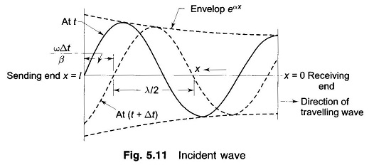
After time Δt, the distribution advances in distance phase by (ωΔt/β) Thus this wave is travelling towards the receiving-end and is the incident wave. Line losses cause its amplitude to decrease exponentially in going from the sending to the receiving-end.
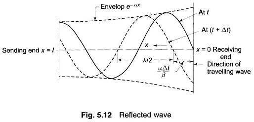
Now
![]()
After time Δt the voltage distribution retards in distance phase by (ωΔt/β). This is the reflected wave travelling from the receiving-end to the sending-end with amplitude decreasing exponentially in going from the receiving-end to the sending-end, as shown in Fig. 5.12.
At any point along the line, the voltage is the sum of incident and reflected voltage waves present at the point [Eq. (5.32)]. The same is true of current waves. Expressions for incident and reflected current waves can be similarly written. If Zc is pure resistance, current waves can be simply obtained from voltage waves by dividing by Zc.
If the load impedance
![]()
i.e. the line is terminated in its characteristic impedance, the reflected voltage wave is zero (VR – ZcIR = 0).
A line terminated in its characteristic impedance is called the infinite line. The incident wave under this condition cannot distinguish between a termination and an infinite continuation of the line.
Power system engineers normally call Zc the surge impedance. It has a value of about 400 ohms for an overhead line and its phase angle normally varies from 0° to — 15°. For underground cables Zc is roughly one-tenth of the value for overhead lines. The term surge impedance is, however, used in connection with surges (due to lightning or switching) or transmission lines and waveguides, where the lines loss can be neglected such that

Surge Impedance Loading (SIL) of a transmission lines and waveguides is defined as the power delivered by a line to purely resistive load equal in value to the surge impedance of the line. Thus for a line having 400 ohms surge impedance,
![]()
where |VR| is the line-to-line receiving-end voltage in kV. Sometimes, it is found convenient to express line loading in per unit of SIL, i.e. as the ratio of the power transmitted to surge impedance loading.
At any time the voltage and current vary harmonically along the line with respect to x, the space coordinate. A complete voltage or current cycle along the line corresponds to a change of 2π rad in the angular argument βx. The corresponding line length is defined as the wavelength.
If β is expressed in rad/m,
![]()
Now for a typical power transmission line
g (shunt conductance/unit length) = 0
![]()
Now time for a phase change of 2π is 1/f s, where f = ω/2π is the frequency in cycles/s. During this time the wave travels a distance equal to λ, i.e. one wavelength.
Velocity of propagation of wave,
![]()
which is a well known result.
For a lossless transmission line (R = 0, G = 0),
![]()
such that α = 0, β = ω(LC)1/2
![]()
and
![]()
For a single-phase transmission line
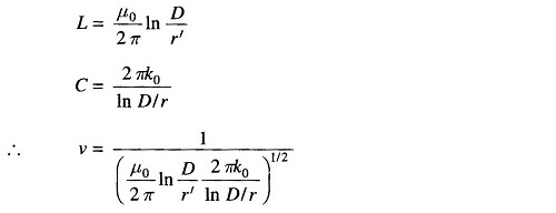
Since r and r’ are quite close to each other, when log is taken, it is sufficiently accurate to assume that
![]()
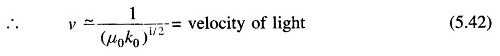
The actual velocity of the propagation of wave along the line would be somewhat less than the velocity of light.
Wavelength of a 50Hz power transmission is approximately given by
![]()