Heavy Current Test Plant:
Heavy Current Test Plant – Simulating the exact fault conditions as would occur in practice is a difficult and a tedious job. The plant for providing the current for these tests as pointed out earlier ought to be of considerable capacity and special design.
To ensure that the behavior of the protection under transient conditions is fully proved, it is often necessary to assemble the complete protective equipment comprising relays, CTs, auxiliary equipment and simulated pilot circuits having appropriate constants. Moreover the gear should remain stable under through fault conditions, i.e. when there is no disparity in the current entering and leaving a protected zone.
Under these conditions the CTs will be subjected to a sudden growth of primary current, with consequent asymmetrical waveform, giving rise to transient d.c. component and may cause saturation in some of the CT cores and ultimately cause maloperation of the protective gear.
Heavy Current Test Plant should therefore be capable of supplying and controlling very heavy currents of pure sinusoidal waveforms in circuits having reactances. In addition to this a point-on-wave control so that the fault could be applied at any point of the voltage wave, and observation and recording arrangement are essential features of a heavy current plant.
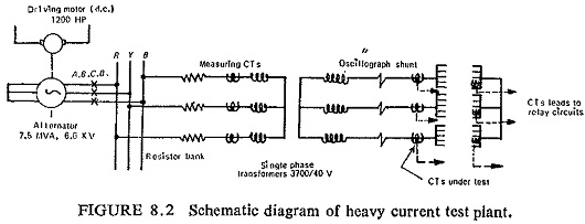
The English Electric Heavy Current Test Plant, schematic diagram shown in Fig. (8.2) comprises a 7.5 MVA, 6.6 KV alternator, driven by 1200 HP d.c. motor feeding heavy current test tables via three single-phase 3700 V/40 V transformers. Provision is made on each of the three test tables for accommodating five pairs of CTs.
In addition accommodation is provided on the high voltage side of the heavy CTs for bushing CTs with bar primaries. The plant provides a maximum current of 50,000 amperes. The X/R ratio has a maximum value of 15 (i.e. a time constant of 48 ms). By means of resistor banks in the high voltage circuit, this can be varied down to an X/R ratio of unity. To keep the a.c. decrements as small as possible, field forcing of the alternator is provided; thus the only variation occurring in the a.c. symmetrical peak value is that due to the change from sub-transient to transient impedance in the alternator.
The test duration and the point-on-wave at which the air blast circuit breaker operates can be controlled, and a complete oscillograph record of each test is printed out automatically.