Frequency Translator using PLL:
The Frequency Translator means shifting the frequency of an oscillator by a small factor. Fig. 2.134 shows the block schematic for frequency translator using PLL.
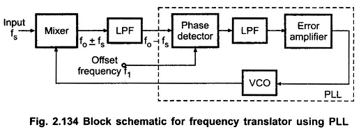
It consists of mixer, low pass filter and the PLL. The input frequency fs which has to be shifted is applied to the mixer. Another input to the mixer is the output voltage of VCO, fo. Therefore, the output of mixer contains the sum and difference signal (fo ± fs). The low pass filter connected at the output of mixer rejects the (fo + fs) signal and gives only (fo – fs) signal at the output. The (fo – fs) signal is applied to the phase detector.
Another input for phase detector is the offset frequency f1. In the locked mode, the VCO output frequency is adjusted to make two input frequencies of phase detector equal.
This gives,
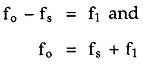
By adjusting offset frequency f1 we can shift the frequency of the oscillator to the desired value.