Classification of Hydraulic Turbines:
The important classification of hydraulic turbines are:
1. According to the type of energy
- Impulse turbine, and
- Reaction turbine
If the energy available at the inlet of the turbine is only kinetic energy, the turbine is known as impulse turbine eg. Pelton wheel. An impulse turbine operates under atmospheric pressure throughout its passage. If water possess both kinetic energy and pressure energy at the inlet of the turbine, then it is known as reaction turbine. eg. Francis turbine and Kaplan turbine. As the water flows through the runner, the pressure energy goes on changing into kinetic energy.
2. According to the direction of flow of water in the runner, the classification of hydraulic turbines are
| (a) Tangential flow turbine – | Water strikes the runner tangentially to its path of rotation (eg. Pelton wheel) |
| (b) Radial flow turbine – | Water flows in radial direction of the runner. The flow may be inward radial ,(Thomson turbine) or outward radial flow (Fourneyron turbine) |
| (c) Axial flow turbine – | Water flows over the vanes in a direction parallel to the axis of rotation of the runner (e.g. Kaplan turbine) |
| (d) Mixed flow turbine – | Water enters radially but leaves in the direction parallel to the axis of rotation of the runner (Modern Francis turbine) |
3. According to the head and quantity of water available, the classification of hydraulic turbines are
| (a) High head turbine – | Works under high head (above 250 m) and requires small quantity of flow (Pei on wheel) |
| (b) Medium head turbine- | Requires medium head (60 to 250 m) and requires relatively large quantity of water (Francis) |
| (c) Low head turbine – | Requires low head (less than 60) and requires very large quantity of water (Kaplan) |
4. According to the position of shaft
- Horizontal turbines – have horizontal shaft (Pelton wheel)
- Vertical turbines – have vertical shafts (Kaplan)
5. According to the specific speed of the turbine,the classification of hydraulic turbines are
- Low specific speed turbines [ 5 < Ns < 60 (Pelton) ]
- Medium specific speed turbines [ 60 < Ns < 300 (Francis) ]
- High specific speed turbines [ Ns > 300 (Kaplan) ]
1. Impulse turbine
Impulse Turbines are those turbines in which the pressure at the exit of nozzles is atmospheric and except for losses, the pressure does not vary along the moving vanes. The thrust experienced by a moving vane of an impulse turbine is solely due to the change in direction of momentum. Pelton wheel is most common hydraulic impulse turbine which works at heads of 150 – 1500 meters.
Pelton wheel (or) pelton turbine is otherwise known as impulse turbine. The essential parts of Impulse turbine and working of impulse turbine is discussed below.
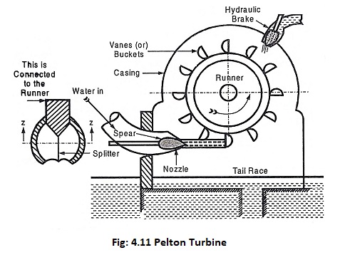
This is a commonly used tangential flow impulse type of turbine. It is suitable for very high heads and requires lesser quantity of water. A Pelton Wheel shown in Fig. 4.11 consists of runner, buckets, nozzle, guide mechanism, hydraulic brake and casing.
(i) Runner and Buckets
The runner is a circular disc which consists of a number of semi-ellipsoidal buckets evenly spaced around its periphery. The buckets are divided into two hemi-spherical cups by a sharp edged ridge known as splitter as shown in Fig 4.11. This arrangement avoids the axial thrust and end thrust on bearings (axial thrusts being equal and opposite). Generally, buckets are bolted to the periphery of the runner. In some cases, the buckets and the wheel are cast integral as one piece. In the case of bolted type, broken or damaged buckets can be replaced economically.
(ii) Nozzle and Guide Mechanism
A nozzle is fitted to the end of the penstock near the turbine. The nozzle is provided with a conical needle or spear to regulate the quantity of water coming out of nozzle, thereby control the speed of the runner. The spear may be operated manually by a hand wheel (for small units) or automatically by a governing mechanism (for larger units).
(iii) Hydraulic Brake
When the turbine has to be brought to rest by closing the inlet valve of the turbine, the runner generally takes a very long time to come to rest due to its inertia. To bring it to rest quickly, a small brake nozzle is provided. This nozzle is opened and it directs a jet of water at the back of the buckets. This acts as a brake to bring the revolving runner quickly to rest.
(iv) Casing
The casing is made of cast iron or fabricated steel plates. It is provided for the following purposes.
- To prevent splashing of water,
- To lead the water to the tail race, and
- To act as a safe guard (cover) against any accidents.
Working of a Pelton Wheel
The water is conveyed to the power house from the head race through penstocks. The nozzle fitted to the end of the penstock (power house end) delivers a high velocity water jet into the buckets. One or more jets of water are arranged to impinge on the buckets tangentially. The impact of water jet on the bucket causes the wheel to rotate, thus producing mechanical work. An electric generator coupled to the runner shaft and mechanical energy is converted into electric power.
After leaving the turbine wheel, water falls into the tail race. The Pelton wheel is located above the tail race so that, the buckets do not splash the tail race water.
2. Reaction turbine
Reaction Turbines are impulse – reaction prime movers. A stator of guide vanes is used to surround the rotor of moving vanes. The guide vanes act as nozzles, allowing only partial expansion of pressure to kinetic energy. Further expansion of pressure head takes place during the motion of fluid over the moving vanes. Hence, the thrust exerted on the blade is partially due to momentum change (impulse) and partly due to pressure action (reaction). As water is admitted all over the wheel periphery through the stator vanes and since the pressure varies across the moving vanes, a reaction turbine is operated completely sealed from atmosphere. A commonly used reaction turbine for medium head (20-200 m) is “Francis Turbine“, the low head (2-3 m) is “Kaplan Turbine“.
Francis Turbine
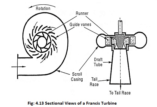
The inward flow reaction turbine having radial discharge at outlet is known as Francis Turbine. In modern Francis turbine, water under pressure enters the runner towards the centre in radial direction and leaves the runner axially. Thus the modern Francis turbine is a mixed flow type turbine.
Working of a Francis Turbine
The water from the reservoir is carried to the turbine through penstocks and enters the scroll casing. The casing distributes water evenly around the circumference of the turbine runner. From the scroll casing, water passes through the stay ring. This ring directs water to the guide vanes. These guide vanes regulate the quantity of water supplied to the runner. The airofoil shape of the guide vanes allow the water to flow smoothly without shock. The water enters the runner with a low velocity and considerable pressure. As the water flows through the runner, the direction of flow of water is changed from axial to radial. The pressure energy is gradually converted into kinetic energy and the runner is rotated at high speed. This torque is transmitted to the generator which is coupled to the runner shaft. After passing through the runner, water enters the tail race through a draft tube.
Axial Flow Reaction Turbines
If water flows parallel to the axis of the rotation of the shaft and the shaft of the turbine is vertical, the turbine is known as axial flow turbine. The lower end of the shaft is known as ‘hub’ or boss. The blades are fixed on the hub and hence hub acts as a runner for axial flow turbines. The types of axial flow reaction turbines are
- Propeller Turbine and
- Kaplan Turbine
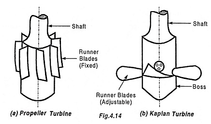
When the blades are fixed on the hub and are not adjustable i.e., the blades are composite with the boss, the turbine is known as propeller turbine. But, if the blades on the boss are adjustable, the turbine is known as Kaplan turbine.
It is suitable for relatively low heads. Hence, it requires a large quantity of water to develop the power.
The main components of a Kaplan turbine are
- Scroll casing
- Guide vanes mechanism
- Hub with blades and
- Draft tube