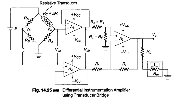
Differential Instrumentation Amplifier Transducer Bridge
Differential Instrumentation Amplifier Transducer Bridge: Figure 14.25 shows a simplified circuit of a Differential Instrumentation Amplifier Transducer Bridge. In this circuit a resistive transducer (whose resistance changes as a function of some physical energy) is…
Comments Off on Differential Instrumentation Amplifier Transducer Bridge
August 20, 2017