Radio Receivers

Receiver Types

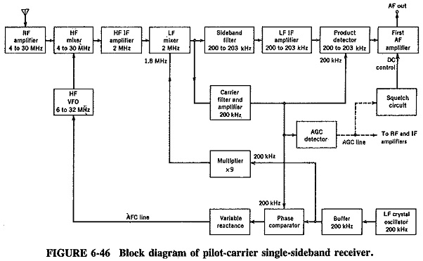
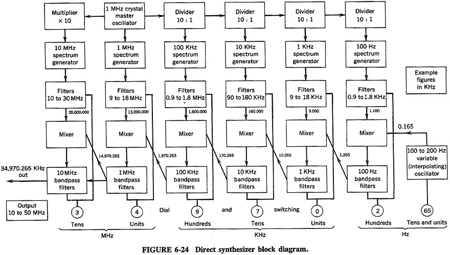
Receiver Types: There are Two Receiver Types namely, Pilot Carrier Receiver and a Suppressed Carrier Receiver; the suppressed carrier receiver incorporates a frequency synthesizer for extra stability and also is used to show how ISB may be demodulated. Pilot Carrier Single Sideband Receiver: As shown in, Figure 6-46, in block form, a pilot-carrier receiver is […]

Receiver Types Read More »

Product Demodulator

Product Demodulator: The Product Demodulator (or detector), as shown in Figure 6-44, is virtually a mixer with audio output. It is popular for SSB, but is equally capable of demodulating all other forms of AM. hi the circuit shown, the input SSB signal is fed to the base via a fixed-frequency IF transformer, and the

Product Demodulator Read More »

Stereo FM Multiplex Reception

Stereo FM Multiplex Reception: Assuming there have been no losses or distortion in transmission, the demodulator output in a Stereo FM Multiplex Reception, tuned to a stereo transmission, will be exactly as shown in Figure 5-10. Increasing in frequency, the signal components will therefore be sum channel (L + R), 19-kHz subcarrier, the lower and

Stereo FM Multiplex Reception Read More »

Ratio Detector Circuit

Ratio Detector Circuit: In the Foster-Seeley discriminator, changes in the magnitude of the input signal will give rise to amplitude changes in the resulting output voltage. This makes prior limiting necessary. It is possible to modify the discriminator circuit to provide limiting, so that the amplitude limiter may be dispensed with. A circuit so modified

Ratio Detector Circuit Read More »

Phase Discriminator

Phase Discriminator: This Phase Discriminator is also known as the center-tuned discriminator or the Foster-Seeley discriminator, after its inventors. It is possible to obtain the same S-shaped response curve from a circuit in which the primary and the secondary windings are both tuned to the center frequency of the incoming signal. This is desirable because

Phase Discriminator Read More »

Slope Detector FM Demodulation

Slope Detector FM Demodulation: Consider a frequency-modulated signal fed to a tuned circuit whose resonant frequency is to one side of the center frequency of the FM signal. The output of this tuned circuit will have an amplitude that depends on the frequency deviation of the input signal; Slope Detector FM Demodulation that is illustrated

Slope Detector FM Demodulation Read More »

FM Receiver Block Diagram

FM Receiver Block Diagram: The FM receiver is a superheterodyne receiver, and the FM Receiver Block Diagram of Figure 6-28 shows just how similar it is to an AM receiver. The basic differences are as follows: Generally much higher operating frequencies in FM Need for limiting and de-emphasis in FM Totally different methods of demodulation

FM Receiver Block Diagram Read More »

Indirect Synthesizer

Indirect Synthesizer: Indirect Synthesizer: The required frequency range in most synthesizers nowadays is obtained from a variable voltage-controlled oscillator (VCO), whose output is corrected by comparison with that of a reference source. This inbuilt source is virtually a direct synthesizer. As shown in Figure 6-26, the phase comparator obtains an output from the VCO, compares

Indirect Synthesizer Read More »

Direct Synthesizer Block Diagram

Direct Synthesizer Block Diagram: A Direct Synthesizer Block Diagram is a piece of apparatus in which multiples and submultiples of a single crystal oscillator frequency are combined by addition and/or subtraction to provide a very wide selection of stable output frequencies. The great advantage of such a system is that the accuracy and frequency stability

Direct Synthesizer Block Diagram Read More »

Scroll to Top