Blocked Rotor Test of Induction Motor
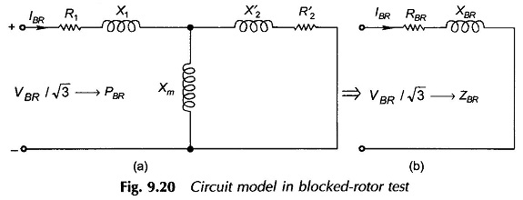
Blocked Rotor Test of Induction Motor: This Blocked Rotor Test of Induction Motor is used to determine the series parameters of the Circuit Model Parameters of an induction motor. The circuit is similar to that…
Comments Off on Blocked Rotor Test of Induction Motor
December 8, 2021