What is a Photodiode?
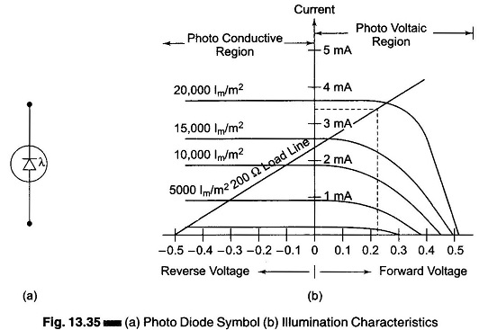
What is a Photodiode?: A reverse biased Semiconductor diode passes only a very small leakage current (a fraction of 1μA in silicon diodes), if the junction is exposed to light. Under illumination, however, the current…
Comments Off on What is a Photodiode?
August 10, 2017