Algorithm for Short Circuit Computation:
So far we have carried out short circuit calculations for simple systems whose passive networks can be easily reduced. In this section we extend our study to large systems. In order to apply the four steps of Algorithm for Short Circuit Computation developed earlier to large systems, it is necessary to evolve a systematic general algorithm so that a digital computer can be used.
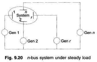
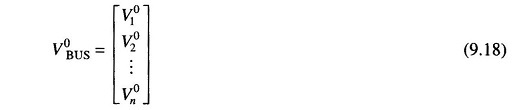
Consider an n-bus system shown schematically in Fig. 9.20 operating at steady load. The first step towards Short Circuit Computation is to obtain prefault voltages at all buses and currents in all lines through a load flow study. Let us indicate the prefault bus voltage vector as
Let us assume that the rth bus is faulted through a fault impedance Zf. The postfault bus voltage vector will be given by
![]()
where
- ΔV is the vector of changes in bus voltages caused by the fault.
As step 2, we drawn the passive Thevenin network of the system with generators replaced by transient/subtransient reactances with their emfs shorted (Fig. 9.21).
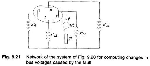
As per step 3 we now excite the passive Thevenin network with – V°r in series with Zf as in Fig. 9.21. The vector ΔV comprises the bus voltages of this network.
Now
![]()
Where
Since the network is injected with current -If only at the rth bus, we have
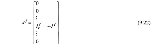
Substituting Eq. (9.22) in Eq. (9.20), we have for the rth bus
![]()
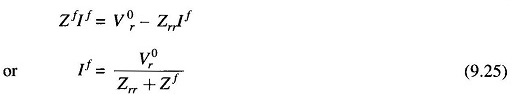
By step 4, the voltage at the rth bus under fault is
![]()
However, this voltage must equal
![]()
We have from Eqs. (9.23) and (9.24)
At the ith bus (from Eqs (9.20) and (9.22))
substituting for If from Eq. (9.25), we have

For i = r in Eq. (9.27)

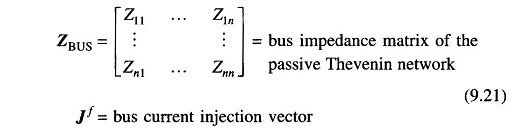
In the above relationship Vi0,s, the prefault bus voltages are assumed to be known from a load flow study. ZBUS matrix of the short-circuit study network of Fig. 9.21 can be obtained by the inversion of its YBUS matrix or the ZBUS building algorithm. It should be observed here that the SC study network of Fig. 9.21 is different from the corresponding load flow study network by the fact that the shunt branches corresponding to the generator reactances do not appear in the load flow study network. Further, in formulating the SC study network, the load impedances are ignored, these being very much larger than the impedances of lines and generators. Of course synchronous motors must be included in ZBUS formulation for the SC study.
Postfault currents in lines are given by
![]()
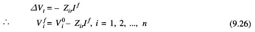
For calculation of postfault generator current, examine Figs. 9.22(a) and (b). From the load flow study (Fig. 9.22(a))
Prefault generator output = PGi + jQGi
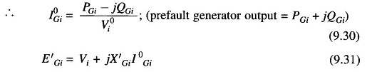
From the SC study, Vfi is obtained, It then follows from Fig. 9.22(b) that