Excitation Phenomenon in Transformer:
It was stated already that the no-load current in a transformer is nonsinusoidal. The basic cause for this Excitation Phenomenon in Transformer, which lies in Transformer Hysteresis and Saturation nonlinearities of the core material, will now be investigated; this can only be accomplished graphically.
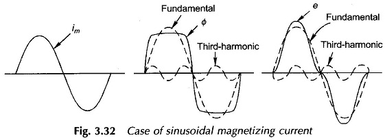
Assume that the voltage v1 applied to the transformer of Fig. 3.5 is sinusoidal. Since the ohmic drop (r1i0) is assumed negligible compared to the magnitude of the applied voltage, the induced emf which balances the applied voltage must also be sinusoidal and so must be the flux established in the core (see Eqs (3.3) and (3.4)). Further, the flux must lag the induced emf by 90° as shown in the emf and flux waveforms drawn in Fig. 3.31. The current necessary to set up sinusoidal flux can be obtained graphically by looking up the Hysteresis curve (Φ-i0 curve) also drawn in Fig. 3.31.
Assume that the steady-state operation has been reached so that hysteresis loop of Fig. 3.31 is being repeated in successive cycles of the applied voltage. Consider the instant when the flux has a value – Φ1, the corresponding exciting current being zero. When the flux becomes zero (at time instant t1), the current is a small positive value i01. When the flux has a positive value Φ2 as shown in the figure, there are two possible values of current, i02 when the flux is on the increasing part of the hysteresis loop and i03 when the flux is on the decreasing part of the loop; i02 > i03. The flux maximum + Φmax coincides with the current maximum + i0 max. The current becomes zero once again for flux + Φ1. So far the positive half of exciting current has been traced out; the negative half will be symmetrical (odd symmetry) to it because of the inherent symmetry of the magnetic hysteresis loop. The complete cycle of the Excitation Phenomenon in Transformer current is sketched in Fig. 3.31.
From the Excitation Phenomenon in Transformer current wave shape of Fig. 3.31, it is observed that it is nonsinusoidal and peaky. While odd symmetry is preserved and the current and flux maximas occur simultaneously, the current zeros are advanced in time with respect to the flux wave shape. As a consequence the current has fundamental and odd harmonics, the strongest being the third harmonic which can be as large as 40% of the fundamental. Further, the fundamental of the exciting current leads the flux by a small angle α0 ; so that the current fundamental has a component in phase with flux and a much smaller component in quadrature to the flux (leading) or in phase with voltage. While Im is responsible for creation of core flux, Ii accounts for the power lost in the core due to hysteresis.
Current Ii must of course be modified to account for the eddy-current loss in the core. The corresponding current component apart from being in phase with V1 is sinusoidal in nature as it balances the effect of sinusoidal eddy-currents caused by the sinusoidal core flux. It is, therefore, seen that eddy-currents do not introduce any harmonics in the exciting current.
When the transformer feeds current to a linear load, the load current is sinusoidal and being much larger than the excitation current would ‘swamp out’ the nonsinusoidalness in the resultant primary current; as a consequence the primary current on load is sinusoidal for all practical purposes.
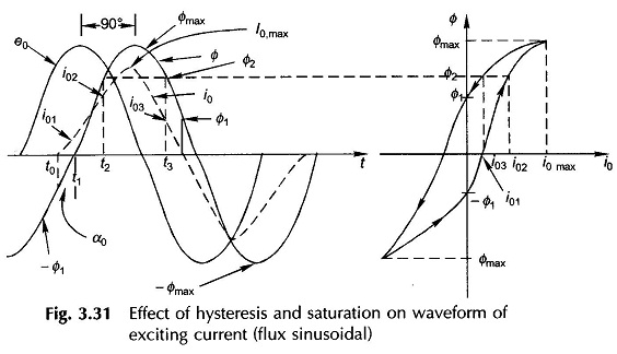
In certain 3-phase transformer connections, third-harmonic current cannot flow, as a result the magnetizing current im is almost sinusoidal. To satisfy the B-H curve, the core flux must then be nonsinusoidal; it is a flat-topped wave. This can be verified by assuming a sinusoidal im and then finding out the Φ wave shape from the Φ-im relationship, the normal magnetizing curve. Since the flux is flat-topped, the emf which is its derivative will now be peaky with a strong third-harmonic content. The various waveforms are illustrated in Fig. 3.32.