DC Traction using Semiconductor Chopper Controlled DC Motors:
Chopper control has replaced resistance control in all dc traction schemes, such as 1500 V dc main line and suburban traction, 750 V dc underground traction and electric buses. The chopper control has following additional advantages over the resistance control:
- Regenerative braking can be carried out almost up to zero speed. Reduction in energy consumption compared to resistance control can be from 30 to 50%.
- With single section of resistance, excellent dynamic braking performance can be obtained.
- Composite braking can be easily implemented.
- Light weight and volume.
- A chopper without provision for regenerative braking is now cheaper than a cam-controller (resistance control).
Traction drives have been built using both dynamic and regenerative brakings but the drives with regenerative braking have been preferred.
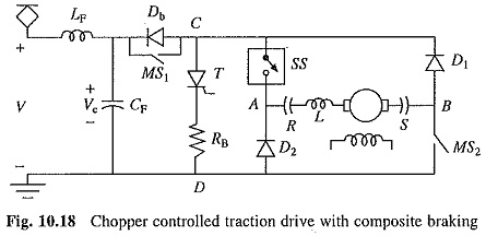
In dc traction, dc supply is obtained by rectifying ac into dc by uncontrolled (diode) rectifiers which permit energy to flow in one direction only, i.e. from ac to dc. When a chopper controlled train is regenerating, the energy regenerated must be absorbed by other trains which are motoring since it cannot be transferred to ac supply. Further, energy regenerated by a train is greater than the energy required by a single train when motoring. This suggests that a DC Traction supply will not be able to always utilise the regenerated energy. If the regenerated energy is pumped into the supply when it cannot use it, the supply voltage rises due to charging of capacitances between line and ground and will lead to insulation failure and damage to the equipment. It is, therefore, necessary that the energy which cannot be utilised is dissipated in a resistance by dynamic braking. The regenerative braking with a provision to dissipate excess energy through dynamic braking is known as composite braking. As regenerative braking of series motor is not reliable, mostly separately excited motor is used in regenerative drives. A chopper controlled drive with composite braking is shown in Fig. 10.18. dc supply feeds the drive through a LF-CF filter which keeps the harmonics in the source current within a tolerable range by filtering out the harmonics generated by the chopper. SS is semiconductor switch, and MS1 and MS2 are the mechanical switches. RS is the reversing switch, which allows reversal of motor connection with respect to terminals A and B. Inductor L is added when the motor armature inductance is not enough to keep the armature current ripple within permissible value and to provide good regenerative braking performance.
The drive operates as follows:
Motoring operation: For motoring operation mechanical switches MS1 and MS2 are kept closed and the semiconductor switch SS is periodically operated. During the on period of the semiconductor switch current flows through the path consisting of source, LF, MS1, SS, L, motor armature and MS2, giving duty interval of the chopper. During the off period of the semiconductor switch, the armature current freewheels through the path consisting of closed switch MS2, D2 and L.
Composite braking: For braking operation mechanical switches MS1 and MS2 are kept open, armature connection is reversed with respect to terminals A and B with the help of the reversing switch RS and the semiconductor switch SS is operated periodically. The polarity of the motor emf is so as to make the terminal B positive with respect to terminal A. During the on period of the semiconductor switch SS, the armature current builds up through the path consisting of diode D1, switch SS and inductance L. During the off period of the switch SS, the armature current flows against the source voltage through the path consisting of diode D1, diode Db, LF, source, diode D2, inductance L and energy is fed to the source. If source does not have enough load to absorb this energy, it flows into capacitor CF increasing its voltage. When capacitor voltage VF: exceeds the source voltage by more than 10%, thyristor T is triggered to connect the braking resistor RB across chopper inputs terminals CD, and the regenerated energy is dissipated in RB. When the switch SS is turned on to start the on period, armature current is transferred to path D1, SS and L, and T is turned off, disconnecting RB, due to want of current. In each cycle of the chopper, during off period of switch SS, first the drive operates in regenerative braking and only when the regeneration is not possible, due to absence of enough load to absorb this energy, dynamic braking is resorted to. Thus, drive regenerates as much energy as the source is capable of absorbing; and what cannot be absorbed by the source is only dissipated by dynamic braking.
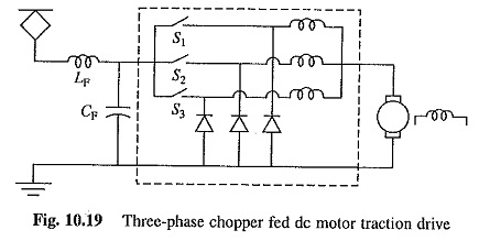
As in case of converter control, the drive is operated with closed-loop current control both during motoring and braking operations. For low power drives required for electric buses and rail cars (single bogie motor coach) transistor (or IGBT) chopper is employed, because transistor chopper operates at a frequency around 2500 Hz. This keeps the motor current ripple low and an inexpensive input filter is required to keep the source current harmonics within a tolerable limit. For higher power ratings required for locomotives and EMUs, thyristor and more recently GTO choppers are used. Because of low frequency operation of these devices (around 300-800 Hz) source current harmonics can pose a problem. Two or three phase choppers are used to overcome these problems. Fig. 10.19 shows a motor fed from a three-phase chopper.