Commutation in DC Machine or Generator or Motor:
One coil each under an adjoining pole-pair is connected between adjacent commutator segments in a lap-wound dc armature, while in a wave-wound armature the only difference is that P/2 coils under the influence of P/2 pole-pairs are connected between adjacent segments. Coil(s) current is constant and unidirectional so long as the coil is under the influence of given pole-pair(s), while it reverses (commutates) when the coil passes onto the next pole-pair as the armature rotates. The process of current reversal called commutation takes place when the coil is passing through the interpolar region (q-axis) and during this period the coil is shorted via the commutator segments by the brush located (electrically) in the interpolar region. Commutation in DC Machine takes place simultaneously for P coils in a lap-wound machine (it has P brushes) and two coil sets of P/2 coils each in a wave-wound machine (electrically it has two brushes independent of P).
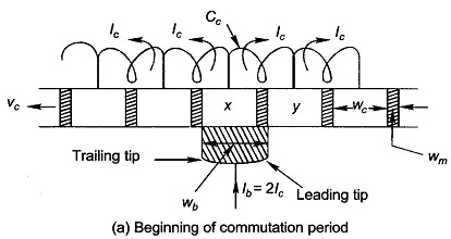
Figure 7.14 shows the schematic diagram of commutator segments in developed form connected to armature coils. Attention will now be focussed on coil Cc as it undergoes commutation.
Various symbols used in the figure are:
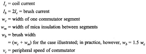
At the instant the commutation of the coil Cc begins, the leading tip of the brush is making full contact with the segment x and is just going to make contact with segment y as shown in Fig. 7.14(a). At this instant all coils to the right of segment x carry current Ic flowing from left to right and those on the left current Ic in the opposite direction. During the period of Commutation in DC Machine as the coil passes from right to the left of the brush, the coil current must reverse.
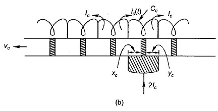
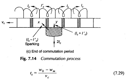
During this period the brush short-circuits the coil via segments x and y as shown in Fig. 7.14(b). The contact width, xc, between brush and segment x reduces linearly while the contact width, yc, between brush and segment y increases. The coil current ic(t) during this period is changing. If at the end of the commutation period, when the trailing tip of the brush is going to break contact with segment x as shown in Fig. 7.14(c), the coil current has not reversed and acquired full value Ic but as I′c < Ic, the breaking of current (Ic – I′c) at the trailing brush tip takes place causing sparking. This is known as under-commutation (or delayed-commutation). It is easy to see from Fig. 7.14, that the period of commutation is given by even when wb > (wc + wm) in which case more than one coil undergoes commutation simultaneously.
Before the causes underlying under-commutation and consequent sparking are explained, the deleterious effects of sparking and why it cannot be tolerated to any large degree may now be studied. Sparking leads to destructive blackening, pitting and wear and eventual burning of commutator copper and brush carbon. It must, therefore, be limited to a tolerable intensity to prolong life of commutator-brush assembly to an acceptable value. As completely sparkless commutation is not possible practically (for reasons advanced below), the carbon brushes must be replaced after some time and less frequently commutator “turned” to a slightly smaller diameter to prepare a fresh clean surface.
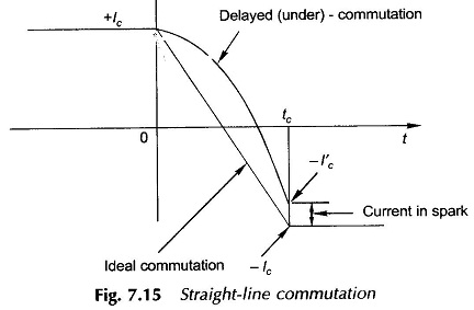
Ideal Commutation:
(also called straight-line commutation) is that in which the current of the commutating coils changes linearly from +Ic to -Ic to in the commutation period as shown in Fig.7.15. The figure also shows delayed Commutation in DC Machine and the current (Ic – I′c) in the spark. In a machine without commutation aids the commutation is delayed for the following reasons:
- The leakage inductance Lc of the coil undergoing commutation has induced in it reactance voltage Lc(dic/dt) which opposes the change in current thereby delaying commutation. Also, usually more than one coil undergo commutation simultaneously, the induced voltage due to mutual inductance among them also tends to prevent current reversal.
- The effect of armature reaction causes shift in MNA from A, B to A’, B’. Since the brushes are located at A, B(GNA’s), a small voltage is induced in the commutating coil. It opposes current commutation (both for generating/motoring machine) as the commutating coil is cutting the flux which has the same sign as that of the pole being left behind.
There are two ways of achieving good commutation—close to straight-line commutation. These are resistance commutation and voltage commutation. The former is always used to give marginal support to the latter.
Resistance Commutation:
High contact resistance between commutator segments and brushes, achieved by using carbon brushes, adds resistance to the circuit of the commutating coil thereby reducing the time-constant (L/R) of the current transient (ic(t)), helping it to change faster in the desired direction. Carbon brushes are invariably used in dc machines. They also help reduce commutator wear and are themselves easily replaceable.
Voltage Commutation:
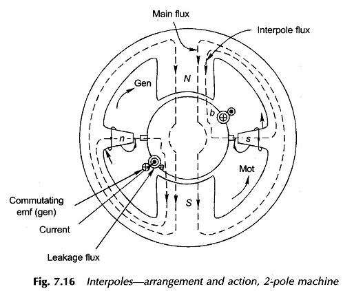
To speed up the Commutation in DC Machine process, the reactance voltage must be neutralized by injecting a suitable polarity dynamical (speed) voltage into the commutating coil. In order that this injection is restricted to commutating coils, narrow interpoles (also called commutating poles or compoles) are provided in the interpolar region. These apply a local correction to the air-gap flux density wave such that a pip of appropriate flux density exists over the commutating coil to induce in it a voltage of the same sign as that of coil current after commutation. For neutralization of reactance voltage at all loads, the interpoles must be excited by armature current by connecting them in series with armature. Arrangement of interpoles, their polarity relative to the main poles, flux pattern of both sets of poles and one commutating coil are shown in Fig. 7.16. It is easy to observe from this figure that polarity of an interpole is that of the main pole ahead in the direction of armature rotation for the generating mode and that of the main pole left behind with respect to the direction of rotation for motoring mode. The interpolar air-gap is kept larger than that of the main pole so that their magnetic circuit is linear resulting in cancellation of the reactance voltage (a linear derivative term) at all loads. Large air-gap results in greater amount of leakage flux which is accommodated by tapering the interpoles with a wider base as shown in Fig. 7.16.
For cancellation of reactance voltage on an average basis
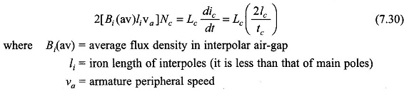
With Bi determined from Eq. (7.30), the ampere-turns needed to cancel the armature reaction ampere-turns and then to create the necessary flux density are given by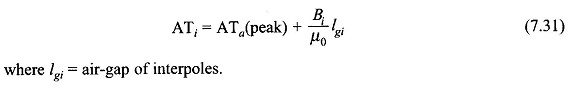
As relationships of Eqs (7.30) and (7.31) are based on sweeping approximation and also accurate estimate of the coil leakage inductance Lc cannot be obtained, the attainment of good commutation is more an empirical art than an analytical science. Furthermore, only good commutation can be achieved but not perfect commutation. One can always observe some sparking at the brushes of a dc machine in operation.
It is not necessary to have interpoles equal to the number of main poles and to reduce cost, especially in low-power dc machines, interpoles of the same polarity are often fitted in alternate interpolar spaces only.