CCIF Intermodulation Distortion:
In the second method of carrying out an CCIF Intermodulation Distortion test, the two test signals used have equal amplitude, and relatively high but slightly different frequencies.
When non-linear distortion is present, a difference frequency component appears in the output and is used as a measure of the amount of distortion present.
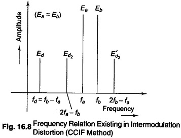
Figure 16.8 illustrates the frequency relations, where fa and fb represent the two test frequencies of amplitude Ea and Eb, and Ed is the amplitude of the resulting difference frequency component fd.
(Second order combination frequencies Ed2 and E’d2 are also shown in
Fig. 16.8, and are a measure of the cubic type of distortion. These components
can however be detected only by the use of a highly selective wave analyzer, and are generally not made use of in this form of the intermodulation test.)
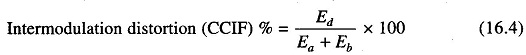
The intermodulation distortion is expressed by the relation
This form of intermodulation test has been recommended by the International Telephonic Consultative Committee, and is referred to by the initials CCIF.
The basic block diagram setup for measuring intermodulation distortion tests by the CCIF method is shown in Fig. 16.9.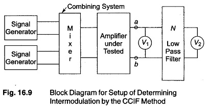
The difference frequency component Ed is separated by a low pass filter N and indicated separately by the voltmeter V2. The amplitude of test signals Ea and Eb can be determined with the help of V1. If V1 is the peak reading instrument, then the peak voltage observed at terminals a — b will be very close to the peak of Ea + Eb.
Alternatively, Ea and Eb can be determined individually if test voltages of frequencies fa and fb are applied one at a time to the input terminals of the amplifier under test. (Both these procedures involve approximation as a result of failure to allow for other frequency components that are simultaneously present at terminals a — b, as a result of the distortion of the amplifier. For exact determination of Ea and Eb, a highly selective wave analyzer is used. However, the approximation procedure is adequate for most practice applications.)
For intermodulation test by the CCIF method, the test frequencies fa and fb are generally centered towards the high frequency end of the response range, and are sometimes placed purposely in the region where the high response begins to fall off appreciably. The difference frequency fd = fb — fa, between the two test frequencies, is generally a moderate value from 50 — 200 Hz. This difference frequency should not be so small as to be below the normal low frequency response range of the amplifier, as the amplifier circuits tends to suppress the difference frequency output.
The intermodulation distortion observed in the CCIF method are indicative of the non-linear distortion present in the system in the frequency range fa to fb.
In particular, the CCIF method is able to measure the result of the non-linear distortion present at the upper frequency limit of the amplifier, where the high response starts to fall off.
The observed value of the intermodulation distortion is substantially independent of the exact values of fa and fb, and of the difference frequency fb — fa = fd) of the two tests, provided this difference frequency is a small fraction of the test frequencies.