AC Load Line of BJT:
AC Equivalent Circuits – Capacitors behave as short-circuits to ac signals, so in the ac equivalent circuit for a transistor circuit all capacitors must be replaced with short-circuits. Power supplies also behave as ac short-circuits, because the dc supply voltage is not affected by ac signals. Also, all power supplies have large-value capacitors at the output terminals, and these will offer short-circuits to ac signals. Substituting short-circuits in place of the power supply and all capacitors in the circuit in Fig. 6-6(a) gives the ac equivalent circuit in Fig. 6-6(b). If RL is present, as shown, it appears in parallel with RC in the ac equivalent circuit of AC Load Line of BJT.
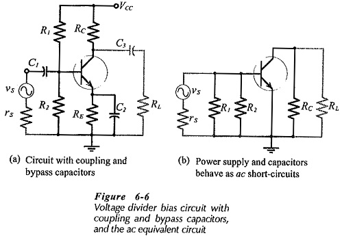
Once the ac equivalent circuit is drawn, the circuit ac performance can be investigated by drawing an AC Load Line of BJT, and by substituting a transistor model in place of the device.
AC Load Lines:
The dc load for the circuit in Fig. 6-6(a) is (RC + RE), consequently, the dc load line is drawn for a total resistance of (RC + RE). Because the emitter resistor is capacitor bypassed in Fig. 6-6(a), resistor RE is not part of the circuit ac load. If external load RL were not present, the circuit ac load would simply be RC. With RL capacitor-coupled to the circuit output, the ac load is RC||RL. An AC Load Line of BJT may now be drawn to represent the circuit ac performance.
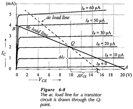
When there is no input signal, the transistor voltage and current conditions are exactly indicated by the Q-point on the dc load line. An ac signal causes the transistor voltage and current levels to vary above and below the Q-point. Therefore, the Q-point is common to both the ac and dc load lines. Starting from the Q-point, another point is found on the AC Load Line of BJT by taking a convenient collector current change (usually ΔIC = ICQ) and calculating the corresponding collector-emitter voltage change (ΔVCE) as shown in Fig. 6-8.