Three Op Amp Instrumentation Amplifier | Block Diagram | Advantages | Applications:
The commonly used Instrumentation Amplifier circuit is one using three op amps. This Three Op Amp Instrumentation Amplifier circuit provides high input resistance for accurate measurement of signals from transducers. In this circuit, a noninverting amplifier is added to each of the basic difference amplifier inputs. The circuit is shown in the Fig. 2.51 (a).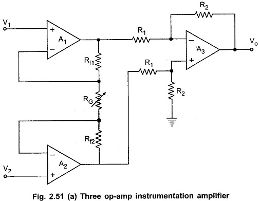
The op-amps A1 and A2 are the noninverting amplifiers forming the input or first stage of the instrumentation amplifier. The op-amp A3 is the normal difference amplifier forming an output stage of the amplifier.
Analysis of Three Op Amp Instrumentation Amplifier:
The block diagram representation of the Three Op Amp Instrumentation Amplifier is shown in the Fig. 2.51 (b).
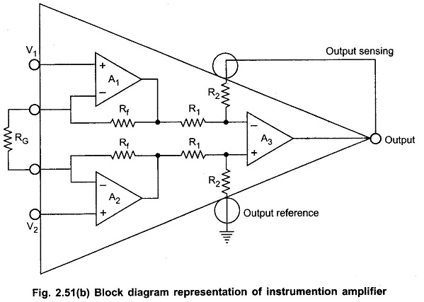
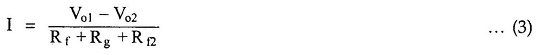
It can be seen that the output state is a standard basic difference amplifier. So if the output of the op-amp A1 is Vo1 and the output of the op-amp A2 is Vo2, we can write,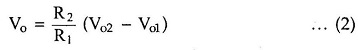
Let us find out the expression for Vo2 and Vo1 interms of V1, V2, Rf1 and Rf2 and RG.
Consider the first stage as shown in the Fig. 2.52.
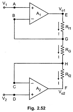
The node A potential of op-amp A1 is V1. From the realistic assumption, the potential of node B is also V1. And hence potential of G is also V1.
The node D potential of op-amp A2 is V2. From the realistic assumption, the potential of node C is also V2. And hence potential of H is also V2.
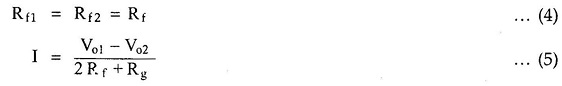
The input current of op-amp A1 and A2 both are zero. Hence current I remains same through Rf1, RG and Rf2.
Applying Ohm’s law between the nodes E and F we get,
Let
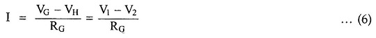
Now from the Observation of nodes G and H,
Equating the two equations (5) and (6),
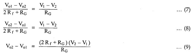
Substituting the Vo2 – Vo1, in the equation (4.81),
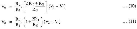
This is the overall gain of the circuit.
Advantages of Instrumentation Amplifier using 3 Op Amp:
- With the help of variable resistance RG, the gain can be easily varied, without disturbing the symmetry of the circuit.
- Gain depends on external resistances and hence can be adjusted accurately and made stable by selecting high quality resistances.
- The input impedance depends on the input impedance of noninverting amplifiers which is extremely high.
- The output impedance is the output impedance of the op-amp A3 which is very very low. This is as required by any instrumentation amplifier.
- The CMRR of the op-amp A3 is very high and most of the common mode signal will be rejected.
- By trimming one of the resistances of the output stage, CMRR can be made extremely high, as required by a good instrumentation amplifier.
Thus the circuit satisfies all the requirements of a good instrumentation amplifier and hence very commonly used in most of the practical applications.
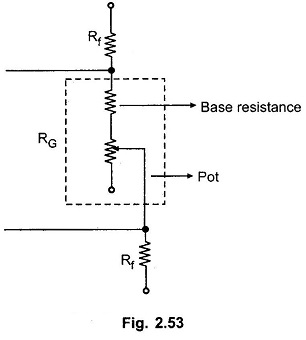
Note : The resistance RG is generally implemented as the series combination of the base resistance and the pot. This is shown in the Fig. 2.53.
Application of Instrumentation Amplifier using 3 Op Amp:
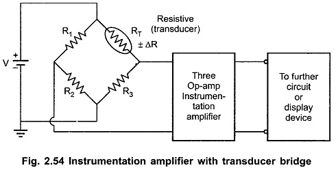
In many industrial applications it is necessary to measure various physical quantities such as temperature, humidity, water flow etc. These are measured by transducers. The output of transducer is required to be amplified for which instrumentation amplifier is used. The Fig. 2.54 shows a practical instrumentation amplifier with a transducer bridge.
Now a days single chip instrumentation amplifiers such as AD521, AD524, LH0036, LH0037 are available.