Solid State Voltmeter:
Solid State Voltmeter – Figure 4.13 shows the circuit of an electronic voltmeter using an IC OpAmp 741C. This is a directly coupled very high gain amplifier. The gain of the OpAmp can be adjusted to any suitable lower value by providing appropriate resistance between its output terminal, Pin No. 6, and inverting input, Pin No. 2, to provide a negative feedback. The ratio R2/R1 determines the gain, i.e. 101 in this case, provided by the OpAmp.
The 0.1 μF capacitor across the 100 k resistance R2 is for stability under stray pick-ups. Terminals 1 and 5 are called offset null terminals. A 10 kΩ potentiometer is connected between these two offset null terminals with its centre tap connected to a – 5V supply. This potentiometer is called zero set and is used for adjusting zero output for zero input conditions.
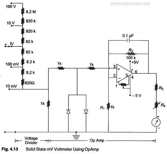
The two diodes used are for IC protection. Under normal conditions, they are non-conducting, as the maximum voltage across them is 10 mV. If an excessive voltage, say more than 100 mV appears across them, then depending upon the polarity of the voltage, one of the diode‘ conducts and protects the IC. A μA scale of 50 – 1000 µA full scale deflection can be used as an indicator. R4 is adjusted to get maximum full scale deflection.