Color Television Receiver Block Diagram
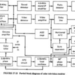
Color Television Receiver Block Diagram: Figure 17-25 shows the block diagram of a Color Television Receiver Block Diagram, but for simplicity the circuits shown in Figure 17-23 are omitted. Interconnection…
Color TV Transmission: Having discussed the manner of indicating luminance and the two components of chrominance in Color TV Transmission, it is now necessary to investigate how they may be,…
Television Horizontal Deflection Circuit: The function performed by these circuits is exactly the same as already described for the vertical deflection circuits. There are some practical differences. The major one…
TV Receiver Synchronizing Circuits: The task of the TV Receiver Synchronizing Circuits is to process received information, in such a way as to ensure that the vertical and horizontal oscillators…
Monochrome Television Receiver Block Diagram: Monochrome Television Receiver Block Diagram as shown in Figure 17-9, TV receivers use the superheterodyne principle. There is extensive pulse circuitry, to ensure that the…
Monochrome Television Transmitter: As shown in the block diagram of Figure 17-2, a Monochrome Television Transmitter system is quite unlike any of the transmission systems studied previously. This section will…
CW Doppler Radar Block Diagram: A simple CW Doppler Radar Block Diagram, such as the one shown in Figure 16-14, sends out continuous sine waves rather than pulses. It uses…
Phased Array Radars: Phased Array Radars - Introduction With some notable exceptions, the vast majority of radars have to cover an area in searching and/or tracking, rather than always being…