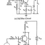
Emitter Bias Circuit Diagram

Emitter Bias Circuit Diagram: This Emitter Bias Circuit Diagram is obtained by simply introducing an emitter resistor to the fixed bias circuit as shown in Fig. 12.9. For analysis, we…

Continue Reading Emitter Bias Circuit Diagram

Series Diode Configurations with DC Inputs

Series Diode Configurations with DC Inputs: The approximate models discussed in preceding section are used for investigation of a number of series diode configurations with dc inputs. This establishes a…

Continue Reading Series Diode Configurations with DC Inputs

Poles and Zeros of Time Domain Response

Poles and Zeros of Time Domain Response: For the given network function, a pole zero plot can be drawn which gives useful information regarding the critical frequencies. The Poles and…

Continue Reading Poles and Zeros of Time Domain Response

Three Phase Balanced Circuit

Three Phase Balanced Circuit: The analysis of Three Phase Balanced Circuit is presented in this section. It is no way different from the analysis of AC systems in general. The…

Continue Reading Three Phase Balanced Circuit