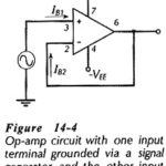
Biasing Bipolar Op Amp Circuit
Biasing Bipolar Op Amp Circuit: Biasing Bipolar Op Amp Circuit - Like other electronic devices, operational amplifiers must be correctly biased if they are to function properly. As already discussed,…
Continue Reading
Biasing Bipolar Op Amp Circuit