Principles of ADC (Analog to Digital Conversion):
Principles of ADC – The input signal is compared with an internally generated voltage which is increased in steps starting from zero. The number of steps needed to reach the full compensation is counted. A simple compensation type is the staircase ramp.
Block diagram of Staircase Ramp Type:
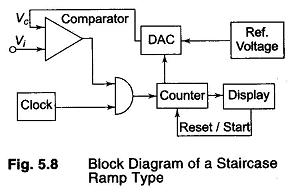
The basic principle is that the input signal Vi is compared with an internal staircase voltage, Vc generated by a series circuit consisting of a pulse generator (clock), a counter counting the pulses and a digital to analog converter, converting the counter output into a dc signal. As soon as Vc is equal to Vi, the input comparator closes a gate between the clock and the counter, the counter stops and its output is shown on the display. The basic block diagram is shown in Fig. 5.8.
Operation of the Circuit:
The clock generates pulses continuously. At the start of a measurement, the counter is reset to 0 at time t1 so that the output of the digital to analog converter (DAC) is also 0. If Vi is not equal to zero, the input comparator applies an output voltage that opens the gate so that clock pulses are passed on to the counter through the gate. The counter starts counting and the DAC starts to produce an output voltage increasing by one small step at each count of the counter. The result is a staircase voltage applied to the second input of the comparator, as shown in Fig. 5.9.
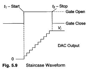
This process continues until the staircase voltage is equal to or slightly greater than the input voltage Vi. At that instant t2, the output voltage of the input comparator changes state or polarity, so that the gate closes and the counter is stopped.
The display unit shows the result of the count. As each count corresponds to a constant dc step in the DAC output voltage, the number of counts is directly proportional to Vc and hence to Vi. By appropriate choice of reference voltage, the step height of the staircase voltage can be determined. For example, each count can represent 1 mV and direct reading of the input voltage in volts can be realized by placing a decimal point in front of the 10 decade.
The advantages of a staircase type DVM are as follows:
- Input impedance of the DAC is high when the compensation is reached.
- The accuracy depends only on the stability and accuracy of the voltage and DAC. The clock has no effect on the accuracy.
The disadvantages are the following:
- The system measures the instantaneous value of the input signal at the moment compensation is reached. This means the reading is rather unstable, i.e. the input signal is not a pure dc voltage.
- Until the full compensation is reached, the input impedance is low, which can influence the accuracy.