Power Swings in Power System Protection:
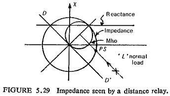
The impedance measured or seen by a distance relay during normal load is shown in Fig. (5.29). Normally this would be outside the tripping zone of the distance relay, but, on a very long line where the length of the line in miles exceeds the system KV, the impedance characteristic may have to be made so large as to involve the point L. Furthermore as the load increases point L moves towards, the relay characteristic in the direction of arrow and during a Power Swings in Power System Protection, it may oscillate up to a point such as PS where it may enter the tripping zone of the relay, even on a medium length line.
Power Swings in Power System Protection are surges of power due to the oscillation of generators with respect to each other which may occur because of changes in load, switching or faults. The presence of a power swing does not necessarily mean that the system is unstable. It is of paramount importance therefore that the relay must distinguish between a fault and a power swing, and respond correctly.
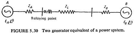
For determining the performance of distance relaying during power swings and out of step conditions let us consider a simple case of Fig. (5.30). The feeder to be protected links the two generators A and B and has an impedance ZL. ZA and ZB are the impedance of the generators A and B respectively. Therefore, the total impedance of the system is
![]()
EA and EB are the voltages behind the transient reactances and are assumed to be constant in magnitude but varying in phase during swings or out of step conditions. The angle δ between EA and EB is therefore a function of the loads on the generators and the system characteristics, taking EB as a reference and EA to be leading EB by an angle δ.
When the steady-state conditions are disturbed due to some reason, power swings occur, and in extreme cases the generators may go out of step. Behavior of the system during power swings is the same as that during initial stages of out-of-step operation. Under these abnormal operating conditions the angle δ will vary until new equilibrium conditions, are established.
For considering the effect of Power Swings in Power System Protection on distance relays, it is better to plot the swing impedance chart on the complex impedance plane. Such a chart represents the swing impedance loci for different values of δ between the emfs of two swinging groups of generators, i.e. EA and EB. The relay operating characteristics and the locus of the impedance seen by the relay during fault conditions can also be represented on the same plane. Such a diagram enables us to see the behavior of relays under different possible conditions such as normal load conditions, power swings, out-of-step operation and faults.
Referring to Fig. (5.30) the impedance seen by the relay during swings and loss of synchronism can be derived as follows:
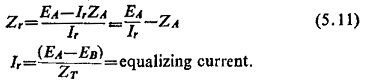
If Zr represents the impedance seen during swing by the relay situated at one end as shown in Fig. (5.30), we get
![]()
where Vr and Ir are voltage and current applied to the relay. Therefore
Assuming the relationship between the magnitudes of the two emfs to be |EA/EB| = K where K is a real number which can be less, equal to or more than unity, Eq. (5.11) becomes:
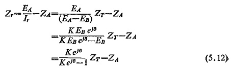
In particular when K=1
![]()
where eJ8 = cos δ = j sin δ
Equation (5.12) represents a family of circles with K as parameter and δ as the variable such that Zr = f(δ). The centres of these circles lie on the straight line colinear with the impedance ZT. If K>1, the centres of the circles Zr = f(δ), i.e. swing impedance loci will be located in the first quadrant; for K<1 the centres will be in the third quadrant; and for K=1 the swing impedance locus is circle with infinite radius, i.e. a straight line which is the perpendicular bisector of the total impedance ZT.
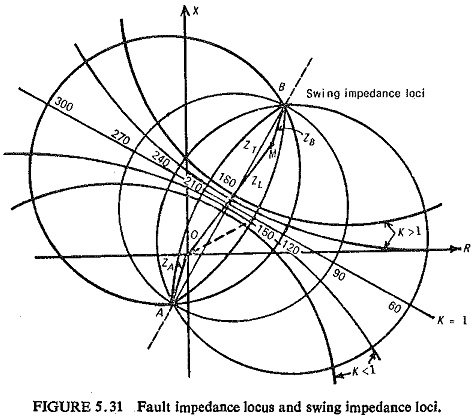
It can also be seen that for constant values of δ and K as variable, the swing impedance loci are circular arcs or a straight line for δ=1800, the ZT itself, with extremities on the ends of the ZT (i.e. A and B). Both these families of the swing impedance loci are orthogonal to each other and these families form the swing impedance chart; one such is shown in Fig. (5.31).
The vector drawn from the origin (relay location) to any point on the impedance chart will represent the impedance seen by the relay Zr. For all practical purposes from protection point of view the swing impedance loci for constant K and variable δ in the first quadrant are almost straight lines parallel to locus for K=1. The effect of power swing is generally seen from the swing impedance locus corresponding to K=1.
The impedance seen by the relay Zr will move along the swing impedance locus during swinging and wherever the swing impedance locus intersects the fault impedance locus, the Zr will be exactly the same as under a three-phase fault. This point is known as the electrical centre of the system and lies approximately midway electrically between the ends of the tie line connecting machines A and B.
It may be noted that the value of 8 determines the mode of operation of the system: (i) for normal operation -0°≤δ≤60°;300°≤δ≤360°; (ii) for swing operation -60°≤δ≤120°;240°≤δ≤300°; (iii) for out-of-step operation -120°≤δ≤240°.
As pointed out earlier, by superimposing the relay characteristics on the swinging chart the effect can be studied.
Prevention of Tripping during Power Swings: If the relay tripping area does not include any part of swing impedance locus, but at the same time is wide enough to include fault resistance, such a relay will not trip during swings, while tripping successfully during faults.
To overcome the maloperation of a distance relay during a swing or overload, the angular range of its pickup characteristic should be reduced so as to enclose only the fault area of a transmission line. This can be achieved by using (a) elliptical relay, (b) use of blinders in conjunction with mho and offset mho units, (c) reversing direction of zone 3 unit of the distance relaying scheme and (d) using a rate of rise of current monitoring relay.