What is an Operational Amplifier?:
An Operational Amplifier is a dc amplifier having a high gain, of the order of 104 – 108. Such an amplifier can perform summing, integration, differentiation, or act as comparator with suitable feedback networks. Hence these are known as opamps. (In such circuits the required response is obtained by the application of negative feedback to a high gain dc amplifier by means of a component connected between input and output terminals, referred to as operational feedback).
An Operational Amplifier is a dc high gain amplifier usually consisting of one or more cascaded differential amplifier stages.
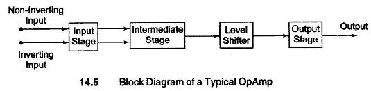
The block diagram of an Operational Amplifier shown in Fig. 14.5 consists of a four stage direct coupled amplifier in cascade. In summarized form, it can be stated as follows.
- The first stage is double ended high gain (60) differential amplifier, i.e. dual input balanced output differential amplifier with a constant current source to increase the common mode rejection. Also this stage generally determines the input resistance of the Operational Amplifier and provides most of the voltage gain.
- The intermediate stage is a single ended differential amplifier, i.e. dual input unbalanced output differential amplifier in order to increase the gain (gain of intermediate stage = 30).
- Since direct coupling is used, the output of the intermediate stage, which is the dc output voltage, is a higher than ground potential when no input is applied. Therefore to bring this dc level to ground potential, a level translator (shifter) circuit is used after the intermediate stage. The third stage used in an emitter follower circuit.
- The final stage is a push-pull complementary amplifier. With low output impedance and minimum offset voltage and currents, the power gain provided is between 5 and 10.
Hence the overall gain of the Operational Amplifier is (60 x 30 x 5 = 9000) which is very large.
The ideal opamp exhibits the following electrical characteristics:
- Infinite voltage gain Aν.
- Infinite input resistance Ri, so that almost any signal source can drive it and there is no loading of the preceding stage.
- Zero output resistance Ro, so that output can drive an infinite number of devices.
- Zero output voltage when input voltage is zero.
- Infinite Bandwidth, so that any frequency signal from zero to infinity Hz can be amplified without attenuation.
- Infinite CMRR, so that common-mode noise voltage is zero.
- Infinite slew rate, so that output voltage changes occur simultaneously with input voltage changes.
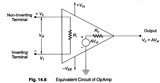
By the use of negative feedback a practical Operational Amplifier can be brought close to some of the above characteristics, such as input resistance, output resistance and bandwidth. The equivalent circuit of an opamp is shown in Fig. 14.6.
The basic operating principles of an opamp can be analyzed with the help of the equivalent circuit shown in Fig. 14.6. The output voltage for Fig. 14.6 is given by
![]()
where
- A = large signal voltage gain.
- Vid = differential input voltage.
- V1 = voltage at Inverting terminal with respect to ground.
- V2 = voltage at non-inverting terminal with respect to ground.
From Eq. (14.1), it is seen that the output voltage is directly proportional to the algebraic difference between the inputs. The opamp amplifies this difference voltage, not the input voltages themselves. For this reason the polarity of the output voltage depends on the polarity of the difference voltage.