Working Principle of Multimeter:
A multimeter is basically a PMMC meter. To measure dc current the meter acts as an ammeter with a low series resistance. Range changing is accomplished by shunts in such a way that the current passing through the meter does not exceed the maximum rated value. A Working Principle of Multimeter consists of an ammeter, voltmeter and ohmmeter combined, with a function switch to connect the appropriate circuit to the D’Arsonval movement.
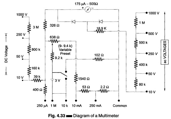
Figure 4.33 shows a meter consisting of a dc milliammeter, a dc voltmeter, an ac voltmeter, a microammeter, and an ohmmeter.
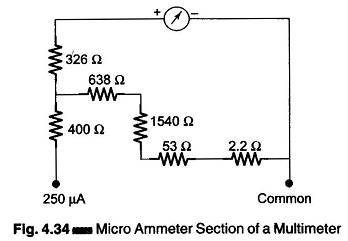
Microammeter:
Figure 4.34 shows a circuit of a multimeter used as a microammeter.
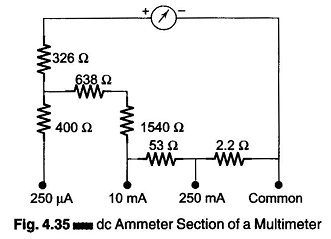
DC Ammeter:
Figure 4.35 shows a working principle of multimeter used as a dc ammeter.
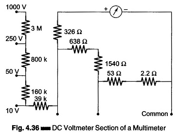
DC Voltmeter:
Figure 4.36 shows the dc voltmeter section of a multimeter.
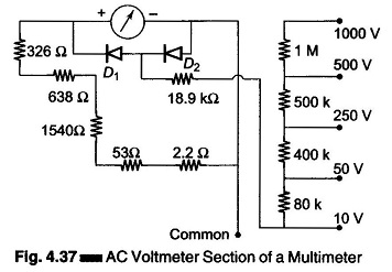
AC Voltmeter:
Figure 4.37 shows the ac voltmeter section of a working principle of multimeter. To measure ac voltage, the output ac voltage is rectified by a half wave rectifier before the current passes through the meter. Across the meter, the other diode serves as protection. The diode conducts when a reverse voltage appears across the diodes, so that current bypasses the meter in the reverse direction.
Ohmmeter:
Referring to Fig. 4.38 which shows the ohmmeter section of a multimeter, in the 10 k range the 102 Ω resistance is connected in parallel with the total circuit resistance and in the 1 MΩ range the 102 Ω resistance is totally disconnected from the circuit.
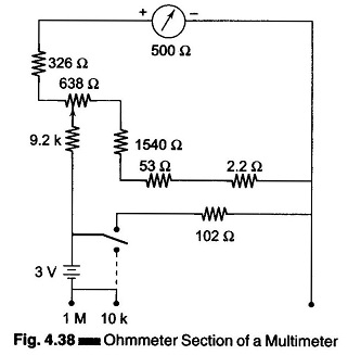
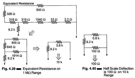
Therefore, on the 1 M range the half scale deflection is 10 k. Since on the 10 k range, the 102 Ω resistance is connected across the total resistance, therefore, in this range, the half scale deflection is 100 Ω. The measurement of resistance is done by applying a small voltage installed within the meter. For the 1 M range, the internal resistance is 10 Ω, i.e. value at mid-scale, as shown in Fig. 4.39. And for the 10 k range, the internal resistance is 100 Ω, i.e. value at mid-scale as shown in Fig. 4.40.
The range of an ohmmeter can be changed by connecting the switch to a suitable shunt resistance. By using different values of shunt resistance, different ranges can be obtained.
By increasing the battery voltage and using a suitable shunt, the maximum values which the ohmmeter reads can be changed.
Multimeter Operating Instructions:
The combination volt-ohm-milliammeter is a basic tool in any electronic laboratory. The proper use of this instrument increases its accuracy and life. The following precautions should be observed.
- To prevent meter overloading and possible damage when checking voltage or current, start with the highest range of the instrument and move down the range successively.
- For higher accuracy, the range selected should be such that the deflection falls in the upper half on the meter scale.
- For maximum accuracy and minimum loading, choose a voltmeter range such that the total voltmeter resistance (ohms per volt x full scale voltage) is at least 100 times the resistance of the circuit under test.
- Make all resistance readings in the uncrowded portion on the meter scale, whenever possible.
- Take extra precautions when checking high voltages and checking current in high voltage circuits.
- Verify the circuit polarity before making a test, particularly when measuring dc current or voltages.
- When checking resistance in circuits, be sure power to the circuit is switched off, otherwise the voltage across the resistance may damage the meter.
- Renew ohmmeter batteries frequently to insure accuracy of the resistance scale.
- Re-calibrate the instrument at frequent intervals.
- Protect the instrument from dust, moisture, fumes and heat.