Motor Protection:
Motor Protection – There is a wide range of motors in existence for various purposes. However, the fundamental problems affecting the choice of protection are independent of the type of motor and the type of load to which it is connected. The motors under discussion here are a.c. motors which include synchronous motors and induction motors.
Types of Faults:
Types of electrical faults in motors are similar to those of generators. Motors therefore in general are protected against the following faults:
- Stator faults.
- Rotor faults.
- Overloads.
- Unbalanced supply voltages including single phasing.
- Undervoltage.
- Reverse or open-phase starting.
- Loss of synchronism (in the case of synchronous motors only).
Stator Protection:
The stator short circuits can be either to earth or between phases. The Motor Protection from these faults is provided with the help of thermal or dash, pot type overcurrent tripping devices giving an inverse time-current characteristic and usually providing instantaneous tripping at high current. Instantaneous overcurrent relays supplied from CTs are provided for motors of larger rating (usually more than 50 HP).
Phase-fault protection is provided by two high-set instantaneous relay elements; the setting is so chosen that it is well above the maximum starting current.
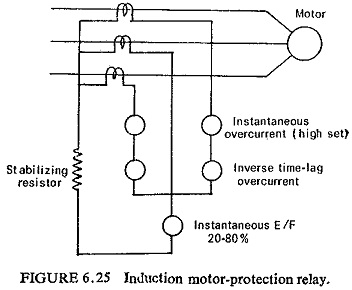
Earth-fault protection for a motor operating on an earthed neutral system is provided by means of a simple instantaneous relay having a setting of approximately 30% of the motor full load current in the residual circuit of three CTs. Operation of relay due to CT saturation during initial high starting current should be avoided. This is usually achieved by increasing the voltage setting of the relay by inserting a stabilizing resistance in series with it. Details of one such scheme applied to an induction motor is shown in Fig. (6.25). When a motor operates on an unearthed neutral system E/F relay as shown in Fig. (6.25) is of no use and a neutral displacement equipment has to be applied.
Differential protection is sometimes provided on very large and important motors in case of unearthed neutral systems.
Rotor Protection:
Any form of unbalance either in the supply voltage or in the loading pattern will cause negative sequence currents to flow in the stator which will induce high frequency currents in the rotor. The frequency of these currents in the rotor is (2 – S) times the nominal frequency of supply. The rotor heating due to the positive sequence component of the stator current is proportional to d.c. resistance value while the heating effect on the rotor windings of the negative sequence component is proportional to (2 – S) f (approximately 100 Hz) a.c. resistance value. Obviously the heating effect of negative phase sequence current is greater than that of the positive phase sequence current. Motor Protection therefore must take this into account if it is to decide correctly what load the motor can stand for a given degree of voltage unbalance without overheating. Types of protections provided for unbalanced voltages will be discussed subsequently. On wound rotor machines some degree of protection against faults in the rotor winding can be obtained by an instantaneous overcurrent relay measuring the stator current.
Overload Protection:
The wide diversity of motor duties and motor designs makes it very difficult to cover all types and ratings of motor with a given characteristic curve. The overload protection is so designed that it matches as closely as possible the heating curve of majority of motors. The protection characteristic should lie just below the heating curve of the motor protected. The protection should preferably have adjustable characteristics so that it may be adopted to different designs of motors and different duties. The protection should not allow the motor to be restarted after tripping while the winding temperature is still high as this may have dangerous consequences. In order to be an effective safeguard an ideal protection should therefore not only match the heating characteristic of the motor but also its cooling characteristic. It must also be ensured that the relay must not operate under heavy starting currents up to say 6 times full load current which can last for a few seconds, half a minute or even longer in exceptional cases. The thermal time constant of most types of motors is of the order of 15 to 20 minutes, hence for protection from overloads the relay should have a time constant slightly lower than this.
When a motor stalls, a current equal to the starting current flows and serious damage results if it persists for a time longer than the starting time. Hence, the closer the characteristic of the overload relay matches the starting current curve the better is the motor protected against such damage.
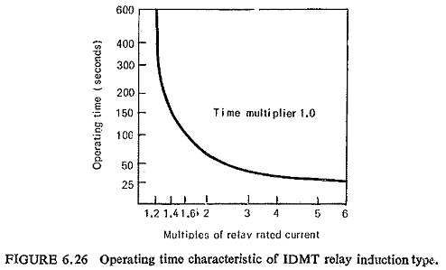
Induction overcurrent relays having characteristic of the type shown in Fig. (6.26) are best suited for such purposes, A typical setting required for overload protection is 120% of full load current. It can be seen from Fig. (6.26) that the current setting is 120% of full load, but a starting current of 6 times full load current for 30 seconds will not cause tripping. With the help of the time multiplier setting the operating time at high values of overcurrent can be adjusted to match the motor starting characteristic without changing the current setting.
One phase-connected relay element is sufficient for overload protection, but two provide single phasing protection as well.
Unbalance and Single Phasing Protection:
The unbalanced three-phase supply causes negative sequence current to flow in the motor which is likely to cause overheating of the machine windings. Unbalanced loads or accidental opening of one phase of the supply (single phasing) depending on the load still keeps the motor running, although such a condition also causes the negative sequence current to flow in the motor.
As pointed out earlier for star connected motors, complete overload and single phasing protection can be provided by fitting two overload elements (Fig. (6.25)). The characteristics of the overload elements arc such that the motor is permitted to run with supply on two phases only until such time as there is a risk of thermal damage. For delta connected motors such an arrangement gives satisfactory protection when the motor is running with more than 70% of full load. For detecting the condition of single phasing a better scheme is to provide a phase-balance relay or bimetal relays as explained below.
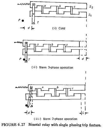
Figure (6.27) shows the bimetal relay having two slides S1 and S2 such that the slider S1 is moved by the deflection of the bimetal strips, whereas the slider S2 is kept in position due to nonbending of the bimetal strips. On symmetrical loading all the three bimetal strips a, b and c bend equally and both the sliders S1 and S2 move in the same direction by a distance d thereby initiating tripping (Fig. (6.27ii)). On single phasing only the two bimetal strips, say a and c bend whereas the third strip b remains cold. The slider S1 is accordingly moved by the heated bimetal strips a and c whereas slider S2 is kept in position by the cold strip b. Thus, this differential motion of the two sliders causes the tripping lever T to move the distance d required for initiating tripping. This operation is shown in
Fig. (6.27iii). It may be noted that although the movement of the slider S1 is to the extent l which is less than d tripping is initiated. Thus, the bimetal relay accordingly responds earlier and protects the motor, also in the critical range of 40-60% when single phasing, which would have remained unprotected by a conventional overload relay.
Sometimes with more important and large motors thermal protection with thermistors is provided. When excessive heating occurs due to overloading or single phasing, the thermistors embedded in the stator causes the tripping as a result of change in the resistance.
Thermistors are small enough to be embedded inside and in direct contact with the motor and windings and they have good thermal response. Their use as temperature sensors, therefore eliminates the delay in transferring heat to actual sensing elements.
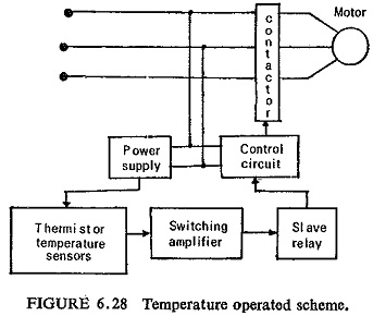
Figure (6.28) illustrates the block diagram of an over temperature protective scheme for a three-phase direct-on-line start type squirrel cage induction motor. Three negative thermal coefficient (NTC) thermistors are located at the hot spots at the surfaces of the three stator winding phases (one on each phase) and are electrically connected into the temperature sensing circuit. The signal from the temperature sensing circuit is fed to a switching amplifier which causes a relay to operate when this signal equals or exceeds a preset level. A normally closed (N/C) contact of this relay is connected in the control circuit. During normal loads the signal from the temperature sensors is below the preset value and the relay is nonoperative. Its N/C contact keeps the control circuit energized and the contactor closed. When the temperature reaches the upper limit the signal from the temperature sensing circuit causes an output in the amplifier and the relay operates to open its contact. The control circuit gets deenergized and the contactor opens to disconnect the motor from supply.
The scheme described above has many advantages such as:
- It can be used for motors of different ratings but of the same class of insulation.
- The temperature at which the relay operates is adjustable.
- An advance warning about the; rising of temperature can be given if three additional thermistors;, set to operate at a slightly lower temperature, are. installed.
- Protection is provided even if one or two of the three thermistors get overheated. Thus the scheme has an inherent capability of protection against single phasing.
- When the temperature of the motor winding and in consequence that of the thermistor has dropped to a low value the relay automatically resets and it is possible to restart it.
Under Voltage Protection:
Operation of motor on undervoltage will generally cause overcurrent and thus can be protected by overload devices or temperature sensitive devices. However, a separate single-element undervoltage relay energized with phase-earth or phase-phase voltage can be provided to protect against a three-phase drop in voltage or an attempt to start with low voltage on all phases. A time delay is usually incorporated to prevent tripping by a transient voltage drop.
Reverse Phase Protection:
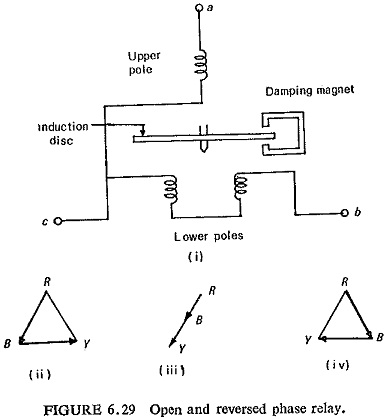
The direction of rotation of the motor changes if the phase sequence is changed. In some motor applications this type of Motor Protection may become an essential feature of motor protection. An induction disc, polyphase voltage relay is used to protect motors from starting with one phase open or with reversed phase sequence. The connections of such a relay are shown in Fig. (6.29), its torque is proportional to the sine product of the two line-to-line voltages. The relay will not close its contacts and hence the motor will not start unless all the three phases are present and in the correct sequence.
Loss of Synchronism:
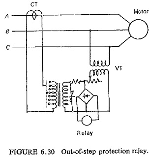
A synchronous motor may pull out of step due to severe overload or due to reduction in supply voltage. Such a condition may be detected by a relay which responds to the change in power factor that occurs when there is pole slipping. One such typical circuit is shown in Fig. (6.30). The voltage between two phases is compared with the current in the third phase; an attracted armature relay energized from a full-wave rectifier bridge is deferentially connected and is in the operated state so long as the motor is in synchronism (step). A nonlinear resistor protects the rectifiers and extends the operating range of the relay.