Setup for Diode Testing in Oscilloscope:
Diode Testing in Oscilloscope -The voltage-current characteristics curve of a crystal diode may be observed using the circuit given in Fig. 7.37 (a).
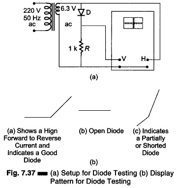
In this case the internal sweep is not used. Horizontal deflection is obtained by connecting the 6.3 V source directly to the horizontal input and switching the sweep control to horizontal amplifier. This provides an horizontal trace that is proportional to the applied voltage and represents the input signal.
The diode current flowing through the 1 kΩ resistance will develop a voltage across the resistance, which is applied to the vertical input terminals. This represents the rectified signal current, since the voltage drop across R is proportional to the diode current.
If the Diode Testing is good, the current through it will be unidirectional, causing the curve to rise vertically from its flat portion. The flat portion represents little or no current in the reverse direction. If the active portion of the curve points downwards, the diode connections should be reversed. The angle between the active and the flat portions of the curve represents the condition of the diode as shown in Fig. 7.37 (b).