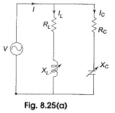
Locus Diagram of Parallel RLC Circuit
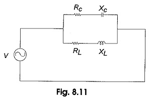
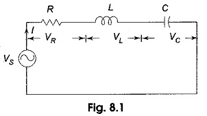
Locus Diagram of Parallel RLC Circuit: (a) Variable XL - Locus plots are drawn for parallel branches containing RLC elements in a similar way as for series circuits. Here we have more than one current…
Comments Off on Locus Diagram of Parallel RLC Circuit
December 25, 2019