Bipolar Junction Transistors Articles:
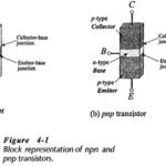
Transistor Operation: pnp and npn Transistor Operation – A junction transistor is simply a sandwich of one type of semiconductor material (p-type or n-type) between two layers of the opposite type. A block representation of a layer of p-type material between two … (Read More)
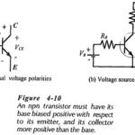
Transistor Voltage and Current: The Transistor Voltage polarities for an npn transistor are shown in Fig. 4-10(a). As well as conventional current direction, the direction of the arrowhead indicates the transistor bias polarities. For an npn transistor, the base is biased … (Read More)
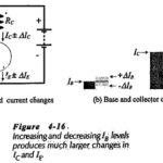
Amplification in Transistor: Current Amplification in Transistor – We already know that a transistor can be used for current amplification. A small change in the base current (ΔIB) produces a large change in collector current (ΔIC) and a large emitter current change … (Read More)
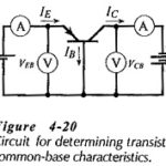
Common Base Transistor Characteristics: To investigate the Common Base Transistor Characteristics of a diode (a two-terminal device), several levels of forward or reverse bias voltage are applied and the resulting current levels are measured. The characteristics of the device are then … (Read More)
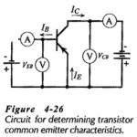
CE Transistor Characteristics: Common Emitter Circuit – Figure 4-26 shows a circuit for determining CE Transistor Characteristics. The input voltage is applied between the B and E terminals, and the output is taken at the C and E terminals. The emitter … (Read More)
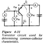
Common Collector Characteristics of BJT: In the Common Collector Characteristics of BJT circuit arrangement of Fig. 4-31, the collector terminal is common to both input CB voltage and output CE voltage. Using this circuit, the common-collector input, output, and current gain … (Read More)

Transistor Testing Circuit: In-Circuit Testing – A quick test to check if a transistor is operational can be performed while the device is still connected in a circuit. Consider Fig. 4-34, which shows a voltmeter connected to measure the transistor collector … (Read More)