Basic Antilog Amplifier Using Diode:
The circuit diagram of basic antilog amplifier using diode is shown in the Fig. 2.70.
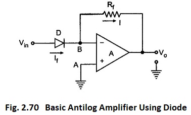
The positions of diode and resistance are exchanged as compared to log amplifier circuit. The node A is grounded and hence node B is at virtual ground. Hence VB = 0.
Now the current flowing through the diode is If and the voltage across diode is Vin itself, as B is at virtual ground. Hence from the diode current equations we can write,
![]()
As op-amp input current is zero, the current I must be same as If.
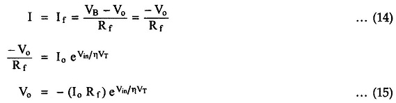
The product Io Rf can be assumed to be Vref, so we get,
![]()
Thus the output voltage is proportional to the exponential function of Vin. The exponential function is nothing but the antilog and thus circuit works as an antilog amplifiers.