Voltage Commutated Chopper Circuit
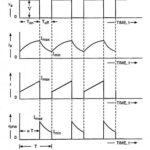
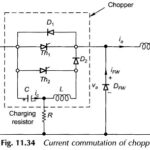
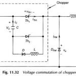
Voltage Commutated Chopper Circuit: This Voltage Commutated Chopper Circuit comprises an auxiliary thyristor Th2, a diode D, inductor L and capacitor C as shown in Fig. 11.32 wherein the total…
Step Down Chopper with RLE Load Working Principle: The choppers are widely employed for speed control of dc motors in industrial and traction drives. Figure 27.30 (a) shows the basic…
Load Commutated Chopper Circuit: In this method of Load Commutated Chopper Circuit, the load current flowing through the thyristor is made to become zero while the motor current is conducted…
Current Commutated Chopper Circuit: Figure 11.34 shows a Current Commutated Chopper Circuit. The main thyristor Th1 of the chopper is commutated by a current pulse generated in the commutation circuitry.…
Load Commutated Inverter Fed Synchronous Motor Drive: Load Commutated Inverter Fed Synchronous Motor Drive is shown in Fig. 10.22. The inverter is a current source inverter employing thyristors T1 - T6. The…
Voltage Source Inverter Control of Induction Motor: Variable frequency and variable voltage supply for induction motor control can be obtained either from a voltage sourve inverter (VSI) or a cycloconverter.…
Reversible Drives using Choppers: Using two quadrant choppers a reversible drive can be achieved, because this combination allows reversal of both current and voltage of the motor termiÂnals. We can…
Two Quadrant Chopper: Sometimes a chopper may be required to provide a two quadrant operation by retaining the current direction in both motoring and braking modes. Such a Two Quadrant…