Hydroelectric Power Station:
A Generating station which utilizes the potential energy of water at a high level for the generation of electrical energy is known as a Hydroelectric Power Station
Hydroelectric Power Station stations are generally located in hilly areas where dams can be built conveniently and large water reservoirs can be obtained. In a Hydroelectric Power Station, water head is created by constructing a dam across a river or lake. From the dam, water is led to a water turbine. The water turbine captures the energy in the falling water and changes the hydraulic energy (i.e., product of head and flow of water) into mechanical energy at the turbine shaft. The turbine drives the alternator which converts mechanical energy into electrical energy. Hydroelectric Power Station are becoming very popular because the reserves of fuels (i.e., coal and oil) are depleting day by day. They have the added importance for flood control, storage of water for irrigation and water for drinking purposes.
Advantages:
- It requires no fuel as water is used for the generation of electrical energy.
- It is quite neat and clean as no smoke or ash is produced.
- It requires very small running charges because water is the source of energy which is available free of cost.
- It is comparatively simple in construction and requires less maintenance.
- It does not require a long starting time like a steam power station. In fact, such plants can be put into service instantly.
- It is robust and has a longer life.
- Such plants serve many purposes. In addition to the generation of electrical energy, they also help in irrigation and controlling floods.
- Although such plants require the attention of highly skilled persons at the time of construction, yet for operation, a few experienced persons may do the job well.
Disadvantages:
- It involves high capital cost due to construction of dam.
- There is uncertainty about the availability of huge amount of water due to dependence on weather conditions.
- Skilled and experienced hands are required to build the plant.
- It requires high cost of transmission lines as the plant is located in hilly areas which are quite away from the consumers.
Schematic Arrangement of Hydroelectric Power Station:
Although a Hydroelectric Power Station simply involves the conversion of hydraulic energy into electrical energy, yet it embraces many arrangements for proper working and efficiency. The schematic arrangement of a modern hydro-electric plant is shown in Fig. 2.2.
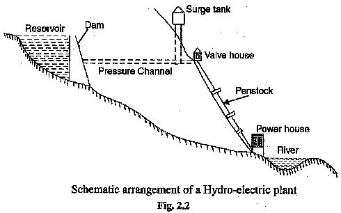
The dam is constructed across a river or lake and water from the catchment area collects at the back of the dam to form a reservoir. A pressure tunnel is taken off from the reservoir and water brought to the valve house at the start of the penstock. The valve house contains main sluice valves and automatic isolating valves. The former controls the water flow to the power house and the latter cuts off supply of water when the penstock bursts, From the valve house, water is taken to water turbine through a huge steel pipe known as penstock. The water turbine converts hydraulic energy into mechanical energy. The turbine drives the alternator which converts mechanical energy into electrical energy.
A surge tank (open from top) is built just before the valve house and protects the penstock from bursting in case the turbine gates suddenly close due to electrical load being thrown off. When the gates close, there is a sudden stopping of water at the lower end of the penstock and consequently the penstock can burst like a paper log. The surge tank absorbs this pressure swing by increase in its level of water.
Choice of Site for Hydro electric Power Stations:
The following points should be taken into account while selecting the site for a Hydroelectric Power Station :
- Availability of water. Since the primary requirement of a Hydroelectric Power Station is the availability of huge quantity of water, such plants should be built at a place (e.g., liver, canal) where adequate water is available at a good head.
- Storage of water. There are wide variations in water supply from a river or canal during the year. This makes it necessary to store water by constructing a dam in, order to ensure the generation of power throughout the year. The storage helps in equalising the flow of water so that any excess quantity of water at a certain period of the year can be made available during times of very low flow in the river. This leads to the conclusion that site selected for a hydro-electric plant should provide adequate facilities for erecting a dam and storage of
- Cost and type of land. The land for the construction of the plant should be available at a reasonable price. Further, the bearing capacity of the ground should be adequate to withstand the weight of heavy equipment to be installed.
- Transportation facilities. The site selected for a hydro-electric plant should be accessible by rail and road so that necessary equipment and machinery could be easily transported.
It is clear from the above mentioned factors that ideal choice of site for such a plant is near a river in hilly areas where dam can be conveniently built and large reservoirs can be obtained.
Constituents of Hydro-electric Plant:
The constituents of a hydro-electric plant are (1) hydraulic structures (2) water turbines and (3) electrical equipment. We shall discuss these items in turn.
- Hydraulic structures. Hydraulic structures in a Hydroelectric Power Station include darn, spillways, headworks, surge tank, penstock and accessory works.
(1) Dam. A dam is a barrier which stores water and creates water head. Dams are built of concrete or stone masonary, earth or rock fill. The type and arrangement depends upon the topography of the site. A masonary dam may be built in a narrow canyon. An earth dam may be best suited for a wide valley. The type of dam also depends upon the foundation conditions, local materials and transportation available, occurrence of earthquakes and other hazards. At most of sites, more than one type of dam may be suitable and the one which is most economical is chosen.
(2) Spillways. There are times when the river flow exceeds the storage capacity of the reservoir. Such a situation arises during heavy rainfall in the catchment area. In order to discharge the surplus water from the storage reservoir into the river on the down-stream side of the dam, spillways are used. Spillways are constructed of concrete piers on the top of the dam. Gates are provided between these piers and surplus water is discharged over the crest of the dam by opening these gates.
(3) Headworks. The headworks consists of the diversion structures at the head of an intake. They generally include booms and racks for diverting floating debris, sluices for by-passing debris and sediments and valves for controlling the flow of water to the turbine. The flow of water into and though headworks should be as smooth as possible to avoid head loss and cavitation. For this purpose, it is necessary to avoid sharp corners and abrupt contractions or enlargements.
(4) Surge tank. Open conduits leading water to the turbine require no protection. However, when closed conduits are used, protection becomes necessary to limit the abnormal pressure in the For this reason, closed conduits are always provided with a surge tank. A surge tank is a small reservoir or tank (open at the top) in which water level rises or falls to reduce the pressure swings in the conduit.
A surge tank is located near the beginning of the conduit. When the turbine is running at a steady load, there are no surges in the flow of water through the conduit i.e., the quantity of water flowing in the conduit is just sufficient to meet the turbine requirements. However, when the load on the turbine decreases, the governor closes the gates of turbine, reducing water supply to the turbine. The excess water at the lower end Of ihe conduit rushes back to the surge tank and increases its water level. Thus the conduit is prevented from bursting. On the other hand, when load on the turbine increases, additional water is drawn from the surge tank to meet the increased load requirement. Hence, a surge tank overcomes the abnormal pressure in the conduit when load on the turbine falls and acts as a reservoir during increase of load on the turbine.
(5) Penstocks. Penstocks are open or closed conduits which carry water to the turbines. They are generally made of reinforced concrete or steel. Concrete penstocks are suitable for low heads (< 30 m) as greater pressure causes rapid deterioration of concrete. The steel penstocks can be designed for any head; the thickness of the penstock increases with the head or working pressure.
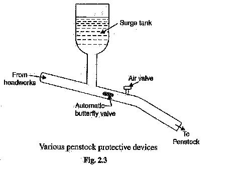
Various devices such as automatic butterfly valve, air valve and surge tank (See Fig. 2.3) are provided for the protection of penstocks. Automatic butterfly valve shuts off water flow through the penstock promptly if it ruptures. Air valve maintains the air pressure inside the penstock equal to outside atmospheric pressure. When water runs out of a penstock faster than it enters, a vacuum is created which may cause the penstock to collapse. Under such situations, air valve opens and admits air in the penstock to maintain inside air pressure equal to the outside air pressure.
Water turbines. Water turbines are used to convert the energy of falling water into mechanical energy. The principal types of water turbines are :
(i) Impulse turbines (ii) Reaction turbines
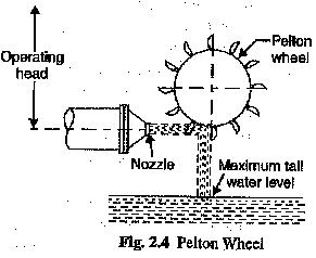
(1) Impulse turbines. Such turbines are used for high heads. In an impulse turbine, the entire pressure of water is converted into kinetic energy in a nozzle and the velocity of the jet drives the wheel. The example of this type of turbine is the Pelton wheel (See Fig. 2.4). It consists of a wheel fitted with elliptical Operating buckets along its periphery. The force of water jet striking the buckets on the wheel drives the turbine. The quantity of water jet falling on the turbine is controlled by means of a needle or spear (not shown in the figure) placed in the tip of the nozzle. The movement of the needle is controlled by the governor. If the load on the turbine decreases, the governor pushes the needle into the nozzle, thereby reducing the quantity of water striking the buckets. Reverse action takes place if the load on the turbine increases.
(ii) Reaction turbines. Reaction turbines are used for low and medium heads. In a reaction turbine, water enters the runner partly with pressure energy and partly with velocity head. The important types of reaction turbines are :
(a) Francis turbines (b) Kaplan turbines
A Francis turbine is used for low to medium heads. It consists of an outer ring of stationary guide blades fixed to the turbine casing and an inner ring of rotating blades forming the runner. The guide blades control the flow of water to the turbine. Water flows radially inwards and changes to a downward direction while passing through the runner. As the water passes over the “rotating blades” of the runner, both pressure and velocity of water are reduced. This causes a reaction force which drives the turbine.