Generation of Switching Surges:
Nowadays in extra high voltage transmission lines and power systems, switching surges is an important factor that affects the design of insulation. All transmission lines rated for 220 kV and above incorporate switching surge spark overvoltage for their insulation levels. A switching surges is a short duration transient voltage produced in the system due to a sudden opening or closing of a switch or circuit breaker or due to an arcing at a fault in the system. The waveform is not unique. The transient voltage may be an oscillatory wave or a damped oscillatory wave of frequency ranging from few hundred hertz to few kilo hertz. It may also be considered as a slow rising impulse having a wave front time of 0.1 to 10 ms, and a tail time of one to several ms. Thus, switching surges contain larger energy than the lightning impulse voltages.
Several circuits have been adopted for producing switching surges. They are grouped as
(i) impulse generator circuit modified to give longer duration wave-shapes,
(ii) power transformers or testing transformers excited by d.c. voltages giving oscillatory waves and these include Tesla coils.
Standard switching impulse Voltage is defined, both by the Indian Standards and the IEC, as 250/2500 μs wave, with the same tolerances for time-to-front and time-to-tail as those for the lightning impulse voltage wave, i.e. time-to-front of (250 ± 50) μs and time-to-half value of (2500 ± 500) μs. Other switching impulse voltage waves commonly used for testing the lightning arresters are 250/1500 μs with a tolerance off ± 500 μs in time-to-half value.
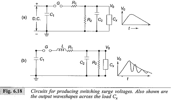
Figure 6.18 shows the impulse generator circuits modified to give switching surges. The arrangement is the same as that of an impulse generator. The values of R1 and R2 for producing waveshapes of long duration, such as 100/1000 µs or 400/4000 µs, will range from 1 to 5 kilo-ohms and 5 to 20 kilo-ohms respectively. Thus, R1 is about 20 to 30% of R2. The efficiency of the generator gets considerably reduced to about 50% or even less. Moreover, the values of the charging resistors R1 are to be increased to very high values as these come in parallel with R2 in the discharge circuit.
The circuit given in Fig. 6.18b produces unidirectional damped oscillations. With the use of an inductor L, the value of R1 is considerably reduced, and the efficiency of the generator increases. The damped oscillations may have a frequency of 1 to 10 kHz depending on the circuit parameters. Usually, the maximum value of the switching surge obtained is 250 to 300 kV with an impulse generator having a nominal rating of 1000 kV and 25 kW sec. Bellaschi et al. used only an inductor L of low resistance to produce switching impulse up to 500 kV. A sphere gap was included in parallel with the test object for voltage measurement and also for producing chopped waves.
where
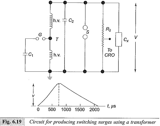
C1 – Surge generator
T – Power transformer
C2 – Load capacitance
Cx – Test object
G – Triggering spark gap
S – Sphere gap
R2 – Potential divider
h.v., l.v. – Transformer high and low voltage windings
Switching surges of very high peaks and long duration can be obtained by using the circuit shown in Fig. 6.19. An impulse generator condenser C1 charged to a low voltage d.c. (20 to 25 kV) is discharged into the low voltage winding of a power or testing transformer. The high voltage winding is connected in parallel to a load capacitance C2, a potential divider R2, a sphere gap S, and test object. Through an autotransformer action, switching surge of proper waveshape can be generated across the test object. The efficiency obtained by this method is high but the transformer should be capable of withstanding very high voltages.
Multi Test Sets for High Voltage Testing:
In many small laboratories like in the teaching institutions, small industries and utility organizations, the requirements of high voltages may be less than about 200 kV, 50 Hz, a.c., 400 kV d.c. and 400 kV standard lightning and switching impulse voltages. The power requirements will be around 5 kW or kVA and the energy requirement will be less than 1.5 kJ. For such applications, flexible and universally interchangeable modular systems of the above voltage and energy ratings are available under different trade names. These systems mainly consist of:
1.a.c. Testing Transformers: With continuous power ratings of 3 to 5 kVA with a short time rating about 150%. The unit can be one single transformer of up to 100 kV (rms), or 2 to 3 units connected in cascade with voltage ratings up to 300 kV (rms).
2.d.c. Units: A.C. transformer with the addition of a rectifier unit and a filter• capacitor, with ripple factor at rated current less than 5% and a voltage drop or regulation less than 10%, for a single stage output of about 100 kV (half-wave rectifier) constitute a d.c. set. D.C. sets are available as multi-stage voltage doubler units with one pulse output, or as a quadruple unit of up to 400 kV rating with the same specifications. In either case, the power ratings will be about 3 to 5 kW continuous. The rectifier stacks used are the selenium diode type.
3.Impulse Voltage Units: Marx circuit of 2 to 4 stages can be assumed using the transformer and d.c. rectifier unit described earlier for an output voltage of about 400 kV (peak) using a one stage rectifier unit. The necessary wave front and wave tail resistors and load capacitances are normally provided. The units are assembled with modular components mounted on suitable insulating columns. The units normally have voltage efficiency of about 90%.
All the basic units are clearly and compactly arranged. By having increased number of units the system can be expanded to obtain higher and desired type of voltage. Control cubicles/boxes are provided for the control and measurement of voltages. The units can be mounted on wheels or located permanently in a test hall of size 4m x 3m x 3m.
Multi-test sets are currently being manufactured and assembled in India by some leading manufacturers of high voltage test equipments.