Control Systems

PLC Programming Languages

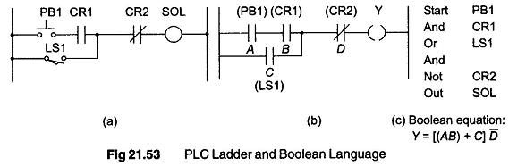
PLC Programming Languages: The term PLC programming languages refers to the method by which the user communicates information to the PLC. The two most common language struc­tures are ladder diagram language and Boolean language. Ladder diagram language is by far the most commonly used PLC Programming Languages.Figure. 21,53, shows a comparsion of the ladder diagram […]

PLC Programming Languages Read More »

Master Control

Master Control: Master control can be considered the emergency stop switches. An emergency stop switch typically is a big red button on a machine that will shut it off in cases of emergency. It is commonly abbreviated as MC/MCR (Master control / Master Control Reset), MCS/MCR (Master Control Set/Master Control reset) or just simply MCR

Master Control Read More »

AC Input

AC Input: The, ac input modules that are commonly available work with 24, 48, 110 and 220 V. It is important to use the one that fits the needs based upon the inputs devices (voltage) used. These day, ac input modules are less common than dc input modules. This is because most of the sensors

AC Input Read More »

DC Inputs

DC Inputs: The, dc inputs modules commonly available will work with 5, 12, 24 and 48 volts. The DC Inputs modules allow us to connect either PNP (sourcing) or NPN (sinking) transistor type devices to them. If using a regular switch (i.e. a toggle or Push Button, etc.) then it is not important whether it is

DC Inputs Read More »

Symbol Counter

Symbol Counter: Symbol Counter – A counter is a simple device used for counting. There are different types of counters. There are up-counters (that only count up 1, 2, 3 …). These are called CTU (Count up), ‘CM’, C or CTR. There are down counters (that only :count downwards, that is, reversed 9, 8, 7). These are

Symbol Counter Read More »

Timer

Timer: Timer is an instruction that waits a set amount of time before doing something. The different kinds of timers are available with different manufacturers. Most of the timers are: ON-delay Timer: This type of timer simply “delays turning on”. In other words after our sensor (input) turns on, the timer waits for some seconds

Timer Read More »

PLC Register

PLC Register: PLC Register – Let us consider a simple example and compare the ladder diagram with its real world external physically connected relay circuit. In Fig. 21.32 (a), the coil circuit will be energized when there is a closed loop between the ‘+’ and ‘—’ terminals of the battery. The same circuit can be drawn

PLC Register Read More »

Relays Definition

Relays Definition: The main purpose of a PLC is to replace real world relays. A Relays Definition is basically an electro-magnetic switch. When a voltage is applied to the coil, a magnetic field is generated. This magnetic field attracts the contact of the relay in, causing them to make a connection. These contacts act like a

Relays Definition Read More »

PLC Applications

PLC Applications: The PLC Applications takes a certain amount of time to react to changes. The total response time of the PLC is a fact that has to be considered while selecting a PLC for some application where speed is a concern. For example, if you take a moment off to look away from this text

PLC Applications Read More »

PLC System Operation

PLC System Operation: A PLC System Operation works by continually scanning a program. This scan cycle can be considered as made up of three important states as shown in Fig. 21.23. In addition there are also more than three states and these are used for checking the system and updating the internal counter and timer

PLC System Operation Read More »

Scroll to Top