Universal Counter Timer:
All measurements of time period and frequency by various circuits can be assembled together to form one complete block, called a Universal Counter Timer.
The universal counter uses logic gates which are selected and controlled by a single front panel switch, known as the function switch. A simplified block diagram is shown in Fig. 6.12.
With the function switch in the frequency mode, a control voltage is applied to the specific logic gate circuitry. Hence, the input signal is connected to the counted signal channel of the main gate.
The selected output from the time base dividers is simultaneously gated to the control F/F, which enables or disables the main gate. Both control paths are latched internally to allow them to operate only in proper sequence.
When the function switch is on the period mode, the control voltage is connected to proper gates of the logic circuitry, which connects the time base signals to the counted signal channel of the main gate. At the same time the logic circuitry connects the input to the gate control for enabling or disabling
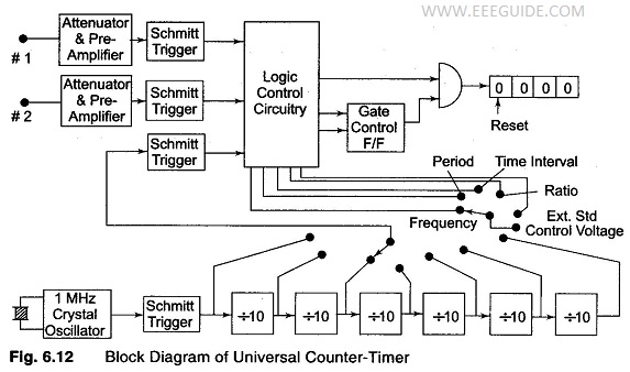
the main gate. The other function switches, such as time interval ratio and external standards perform similar functions. The exact details of switching and control procedures vary from instrument to instrument.