Short Circuit of a Synchronous Machine on No Load:
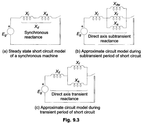
Short Circuit of a Synchronous Machine on No Load – Under steady state short circuit conditions, the armature reaction of a synchronous generator produces a demagnetizing flux. In terms of a circuit this effect is modelled as a reactance Xa in series with the induced emf. This reactance when combined with the leakage reactance Xl of the machine is called synchronous reactance Xd (direct axis synchronous reactance in the case of salient pole machines). Armature resistance being small can be neglected. The steady state short circuit model of a Synchronous Machine on No Load is shown in Fig. 9.3a on per phase basis.
Consider now the sudden short circuit (three-phase) of a synchronous generator initially operating under open circuit conditions. The machine undergoes a transient in all the three phase finally ending up in steady state conditions described above.
The circuit breaker must, of course, interrupt the current much before steady conditions are reached. Immediately upon short circuit, the DC off-set currents appear in all the three phases, each with a different magnitude since the point on the voltage wave at which short circuit occurs is different for each phase. These DC off-set currents are accounted for separately on an empirical basis and, therefore, for short circuit studies, we need to concentrate our attention on symmetrical (sinusoidal) short circuit current only.
Immediately in the event of a short circuit, the symmetrical short circuit current is limited only by the leakage reactance of the machine. Since the air gap flux cannot change instantaneously (theorem of constant flux linkages), to counter the demagnetization of the armature short circuit current, currents appear in the field winding as well as in the damper winding in a direction to help the main flux. These currents decay in accordance with the winding time constants.
The time constant of the damper winding which has low leakage inductance is much less than that of the field winding, which has high leakage inductance. Thus during the initial part of the short circuit, the damper and field windings have transformer currents induced in them so that in the circuit model their reactances—Xf of field winding and Xdw of damper winding—appear in parallel with Xa as shown in Fig. 9.3b. As the damper winding currents are first to die out, Xdw effectively becomes open circuited and at a later stage Xf becomes open circuited. The machine reactance thus changes from the parallel combination of Xa, Xf and Xdw during the initial period of the short circuit to Xa and Xf in parallel (Fig. 9.3c) in the middle period of the short circuit, and finally to Xa in steady state (Fig. 9.3a). The reactance presented by the machine in the initial period of the short circuit, i.e.
![]()
is called the subtransient reactance of the machine. While the reactance effective after the damper winding currents have died out, i.e.
![]()
is called the transient reactance of the machine. Of course, the reactance under steady conditions is the synchronous reactance of the machine. Obviously X″d<X′d<Xd. The machine thus offers a time-varying reactance which changes from X″d to X′d and finally to Xd.
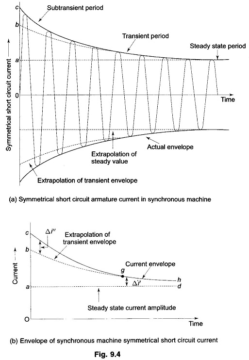
If we examine the oscillogram of the short circuit current of a Synchronous Machine on No Load after the DC off-set currents have been removed from it, we will find the current wave shape as given in Fig. 9.4a. The envelope of the current wave shape is plotted in Fig. 9.4b. The short circuit current can be divided into three periods—initial subtransient period when the current is large as the machine offers subtransient reactance, the middle transient period where the machine offers transient reactance, and finally the steady state period when the machine offers synchronous reactance.
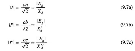
If the transient envelope is extrapolated backwards in time, the difference between the transient and subtransient envelopes is the current Δi″ (corresponding to the damper winding current) which decays fast according to the damper winding time constant. Similarly, the difference Δi′ between the steady state and transient envelopes decays in accordance with the field time constant.
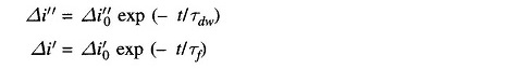
In terms of the oscillogram, the currents and reactances discussed above, we can write
where
- |I| = steady state current (rms)
- |I′| = transient current (rms) excluding DC component
- |I′′| = subtransient current (rms) excluding DC component
- Xd = direct axis synchronous reactance
- X′d = direct axis transient reactance
- X′′d = direct axis subtransient reactance
- |Eg| = per phase no load voltage (rms)
- Oa, Ob, Oc = intercepts shown in Figs. 9.4a and b.
The intercept Ob for finding transient reactance can be determined accurately by means of a logarithmic plot. Both Δi″ and Δi′ decay exponentially as
where Tdw and Tf are respectively damper, and field winding time constants with Tdw ≪ Tf . At time t ≫ Tdw, Δi″ practically dies out and we can write
![]()
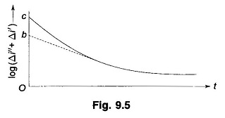
The plot of log (Δi″ + Δi′) versus time for t ≫ Tdw therefore, becomes a straight line with a slope of (- Δi′0/Tf) as shown in Fig. 9.5. As the straight line portion of the plot is extrapolated (straight line extrapolation is much more accurate than, the exponential extrapolation of Fig. 9.4), the intercept corresponding to t = 0 is
![]()
where
- ra = AC resistance of the armature winding per phase.
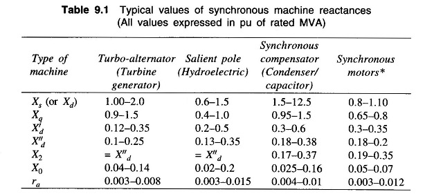
Though the machine reactances are dependent upon magnetic saturation (corresponding to excitation), the values of reactances normally lie within certain predictable limits for different types of machines. Table 9.1 gives typical values of machine reactances which can be used in fault calculations and in stability studies.
Normally both generator and motor subtransient reactances are used to determine the momentary current flowing on occurrence of a short circuit. To decide the interrupting capacity of circuit breakers, except those which open instantaneously, subtransient reactance is used for generators and transient reactance for synchronous motors.