Band Reject Filter Circuit
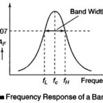
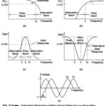
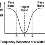
Band Reject Filter Circuit: In this Band Reject Filter Circuit, frequencies are attenuated in the stop band and passed outside it, as shown in Fig. 15.20(b). As with band pass…
Band Pass Filter Circuit Diagram: A Band Pass Filter Circuit Diagram designed to pass signals only in a certain band of frequencies while rejecting all signals outside this band. There…
Higher Order Filter Design: Higher Order Filter Design - From the preceding discussion on filters we can conclude that in the stop band the gain of the filter changes at…
Second Order High Pass Butterworth Filter Derivation: As in the case of a first order filter, a second order high pass filter can be formed from a second order low…
First Order High Pass Butterworth Filter Derivation: First Order High Pass Butterworth Filter Derivation - High pass filters are often formed by interchanging frequency determining resistors and capacitors in a…
Second Order Low Pass Butterworth Filter Derivation: A stop band response having a 40 db/decade roll off is obtained with a Second Order Low Pass Butterworth Filter Derivation A second…
Low Pass Filter Circuits: The Low Pass Filter Circuits of Fig. 15.7 is commonly used for low pass active filters. The filtering is done by the use of an RC…
Classification of Active Filters: An electric filter is often a frequency selective circuit that passes a specified band of frequencies and blocks or attenuates signals of frequencies outside this band.…