Pin Diagram of 80286 Microprocessor
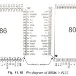
Pin Diagram of 80286 Microprocessor: The Pin Diagram of 80286 Microprocessor is available in 68-pin PLCC (Plastic Leaded Chip Carrier), 68-pin Ceramic LCC (Lead Less Chip Carrier) and 68-pin PGA…
Series and Shunt Compensation of Transmission Lines: The performance of long EHV AC transmission systems can be improved by reactive compensation of series or shunt (parallel) type. Series capacitors and…
Blocked Rotor Test of Induction Motor: This Blocked Rotor Test of Induction Motor is used to determine the series parameters of the Circuit Model Parameters of an induction motor. The…
Performance of CMOS Gates: The Performance of CMOS Gates which based on following different categories namely, Operating Speed : Slower than TTL series. Approximately 25 to 100 ns depending on…
CMOS NAND Gate Circuit Diagram: Fig. 3.3 shows CMOS NAND Gate Circuit Diagram 2-input NAND gate. It consists of two P-channel MOSFETs, Q1 and Q2, connected in parallel and two…
Conditions For Driving Point Function: The restrictions on pole and zero locations in the Conditions For Driving Point Function with common factors in P(s) and Q(s) cancelled are listed below.…
Reactive Power with Wattmeter: We have already seen earlier that the difference between higher reading wattmeter and lower reading wattmeter yields VLIL sin Φ. So, the total reactive power =…
Leading Power Factor Load: Suppose the load in Fig. 9.46(a) is capacitive, the wattmeter connected in the leading phase would read less value. In that case, WR will be the…