Pressure Inductive Transducer

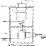
Pressure Inductive Transducer: Pressure Inductive Transducer - A simple, arrangement, wherein a change in the inductance of a sensing element is produced by a pressure change, is given in Fig.…

Continue Reading Pressure Inductive Transducer

Resistance Thermometer Working Principle

Resistance Thermometer Working Principle: The resistance of a conductor changes when its temperature is changed. This property is utilized for the measurement of temperature. The Resistance Thermometer working principle is…

Continue Reading Resistance Thermometer Working Principle

Wheatstone Bridge Diagram

Wheatstone Bridge Diagram: A Wheatstone Bridge diagram in its simplest form consists of a network of four resistance arms forming a closed circuit, with a dc source of current applied…

Continue Reading Wheatstone Bridge Diagram

Megger Circuit Diagram

Megger Circuit Diagram: Another common method of measuring resistances above 50 M Ω is the Megger Circuit Diagram (megaohmmeter) shown in Fig. 10.23(a). This instrument is used to measure very…

Continue Reading Megger Circuit Diagram

Vector Impedance Meter (Direct Reading)

Vector Impedance Meter (Direct Reading): If some knowledge of the reactive and resistive factors is needed, in addition to obtaining a direct reading of the magnitude of the impedance (Z),…

Continue Reading Vector Impedance Meter (Direct Reading)

Multirange Ohmmeter

Multirange Ohmmeter: The Multirange Ohmmeter circuit shown in Fig. 4.28 (a) is only for a single range of resistance measurement. To measure resistance over a wide range of values, we…

Continue Reading Multirange Ohmmeter