Transformer Coupled Amplifier
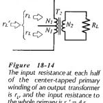
Transformer Coupled Amplifier: Transformer Coupled Amplifier commences with the load resistance and output power, specification. A signal voltage amplitude may also be stated, as well as the upper and lower…
Operational Amplifier Circuit Stability: Loop Gain and Loop Phase Shift - Consider the inverting amplifier circuit and waveforms in Fig. 15-Â1(a). The signal voltage voltage (vs) is amplified by a…
Instrumentation Amplifier Circuit Working: Circuit Operation - At first glance, the Instrumentation Amplifier Circuit Working in Fig. 14-28 looks complex, but when considered section by section it is found to…
Direct Coupled Inverting Amplifier: The circuit in Fig. 14-18 is termed an Direct Coupled Inverting Amplifier because, with Vi applied via R1 to the inverting input terminal, the output goes negative when…
Non Inverting Amplifier Theory: Direct-Coupled Noninverting Amplifier - The Non Inverting Amplifier Theory circuit in Fig. 14-14 behaves similarly to a voltage follower circuit with one major difference. Instead of…
Integrated Circuit Operational Amplifier: Circuit Symbol and Packages - Figure 14-1(a) shows the triangular circuit symbol for an Integrated Circuit Operational Amplifier (op-amp). As illustrated, there are two input terminals,…
Emitter Current Feedback Circuit: Emitter Current Feedback Circuit is produced by connecting an unbypassed resistor in series with the emitter terminal of a transistor, as shown in Fig. 13-24(a). The…
Two Stage Direct Coupled BJT Amplifier Circuit: The Two Stage Direct Coupled BJT Amplifier Circuit in Fig. 13-17 is reproduced from Fig. 12-22, and modified to include feedback components RF1Â and…