Per Unit System in Power System:
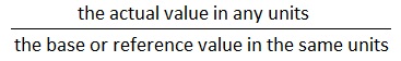
Per Unit System in power system is usual to express voltage, current, voltamperes and impedance of an electrical circuit in per unit (or percentage) of base or reference values of these quantities. The per unit value of any quantity is defined as:
The Per Unit System in Power System is convenient on various sections of a power system are connected through transformers and have different voltage levels.
Consider first a single-phase system.
Let

Then


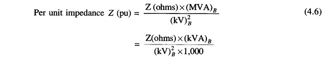
If the actual impedance is Z (ohms), its per unit value is given by

For a power system, practical choice of base values are:
![]()
or


In a three-phase system rather than obtaining the per unit values using per phase base quantities, the per unit system in power system values can be obtained directly by using three-phase base quantities. Let
Three-phase base megavoltamperes = (MVA)B
Line-to-line base kilovolts = (kV)B
Assuming star connection (equivalent star can always be found),


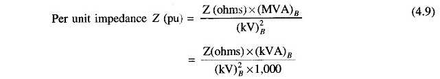
When MVA base is changed from (MVA)B, old to (MVA)B, new and KV base is changed from (KV)B, old to (KV)B, new, the new per unit impedance from Eq. (4.9) is given by

Per Unit System in Transformer:
It has been said already that a three-phase transformer forming part of a three-phase system can be represented by a single-phase transformer in obtaining per phase solution of the system. The delta connected winding of the transformer is replaced by an equivalent star so that the transformation ratio of the equivalent single-phase transformer is always the line-to-line voltage ratio of the three-phase transformer.
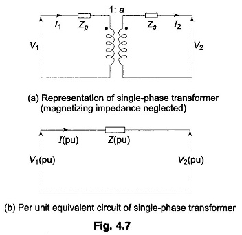
Figure 4.7a represents a single-phase transformer in terms of primary and secondary leakage reactances Zp and Zs and an ideal transformer of ratio 1 : a. The magnetizing impedance is neglected. Let us choose a voltampere base of (VA)B and voltage bases on the two sides of the transformer in the ratio of transformation, i.e.

Therefore,

From Fig. 4.7a we can write
![]()
We shall convert Eq. (4.12) into per unit form

Dividing by V2B throughout and using base relations (4.11 a, b, c), we get
![]()
Now

Equation (4.13) can therefore be written as
![]()
where
![]()
Equation (4.14) can be represented by the simple equivalent circuit of Fig. 4.7b which does not require an ideal transformer. Considerable simplification has therefore been achieved by the per unit method with a common voltampere base and voltage bases on the two sides in the ratio of transformation.
Z(pu) can be determined directly from the equivalent impedance on primary secondary side of a transformer by using the appropriate impedance base.
On primary side:

But

On secondary side:
![]()

Thus the per unit impedance of a transformer is the same whether computed from primary or secondary side so long as the voltage bases on the two sides are in the ratio of transformation (equivalent per phase ratio of a three-phase transformer which is the same as the ratio of line-to-line voltage rating).
The pu transformer impedance of a three-phase transformer is conveniently obtained by direct use of three-phase MVA base and line-to-line kV base in relation (4.9). Any other impedance on either side of a transformer is converted to pu value just like Zp or Zs.