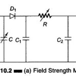
Field Strength Meter (Transistor) Circuit
Field Strength Meter (Transistor) Circuit: The Field Strength Meter is used to measure the radiation intensity from a transmitting antenna at a given location. With its own small antenna, it…
Continue Reading
Field Strength Meter (Transistor) Circuit