CE Transistor Characteristics
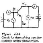
CE Transistor Characteristics: Common Emitter Circuit - Figure 4-26 shows a circuit for determining CE Transistor Characteristics. The input voltage is applied between the B and E terminals, and the…
Common Base Transistor Characteristics: To investigate the Common Base Transistor Characteristics of a diode (a two-terminal device), several levels of forward or reverse bias voltage are applied and the resulting…
Amplification in Transistor: Current Amplification in Transistor - We already know that a transistor can be used for current amplification. A small change in the base current (ΔIB) produces a large…
Transistor Voltage and Current: The Transistor Voltage polarities for an npn transistor are shown in Fig. 4-10(a). As well as conventional current direction, the direction of the arrowhead indicates the…
Transistor Operation: pnp and npn Transistor Operation - A junction transistor is simply a sandwich of one type of semiconductor material (p-type or n-type) between two layers of the opposite type.…
Vertical Deflection Circuit in TV: The Vertical Deflection Circuit in TV include the vertical oscillator and amplifier for vertical scanning at 60 Hz and a similar horizontal arrangement for scanning…
Monochrome Television Receiver Block Diagram: Monochrome Television Receiver Block Diagram as shown in Figure 17-9, TV receivers use the superheterodyne principle. There is extensive pulse circuitry, to ensure that the…
High Frequency Limitations: As stated, transistors suffer from High Frequency Limitations. These are of a twofold nature. On the one hand, there are the same difficulties as those encountered with…