DC Motor Losses and Efficiency:
The Losses and Efficiency of a transformer have been studied in earlier lesson. As in the case of transformers, it is more accurate to determine the DC Motor Losses and Efficiency rather than by the direct load test in which the input and output are required to be measured. Furthermore, in large and even in medium-size machines, it is not practically possible to arrange for the actual loading of the machine. Once the losses have been determined, the machine efficiency (ID can be computed from the relationships:
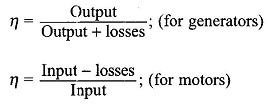
The efficiency thus determined is more accurate because the error involved is only in losses, whereas in the direct method there is error in measurement of both the input and output.
The study of DC Motor Losses and Efficiency is essential for design purposes because (i) losses directly influence the economy of operation of the machine; and (ii) the rating of a machine depends on the maximum temperature that the insulation can withstand, which in turn is dictated by the heat developed in the core and conductors by the losses. Of course, the rating of a machine for a given frame size and losses can be raised by proper design of the ventilation system.
The process of energy conversion in DC Motor Losses and Efficiency involves currents, fluxes and rotation which cause losses in conductors and ferromagnetic materials, and mechanical losses of rotation. Various losses can be classified conveniently by the tree-diagram shown in Fig. 5.50.
Constant Losses:
A machine is normally designed to run at constant voltage mains and at a substantially constant speed (variable speeds are also required for certain applications). As a result, some of the losses remain nearly constant in the working range of the machine and are, therefore, named constant losses. The constant losses can be further classified as no-load core-loss and mechanical-loss.

No–load Core (Iron)–Loss:
This loss consists of hysteresis and eddy-current loss caused by changing flux densities in the iron core of the machine when only the main winding is excited. The core-loss is largely confined to the armature of a dc machine, the armature of a synchronous machine and the stator of an induction machine. The frequency of flux density variation in the rotor core of the induction machine is so low (sf) under normal operating conditions that it has negligible core-loss.
While in the case of transformers the core-loss arises because of time-variation of the flux density with the axis of flux remaining fixed; in the case of rotating machines, this loss results from both time-variation of the flux density and rotation of its axis. As a consequence the specific core-loss is larger in rotating machines than that in transformers.
The time- and axis-variation of the flux density in a DC Motor Losses and Efficiency is illustrated by means of the cross-sectional view of a dc machine as shown in Fig. 5.51. It is easily seen from this figure that as the machine armature rotates, the flux density in the elemental volume of the core shown shaded varies cyclically in magnitude as well as in direction.

Additional hysteresis and eddy-current loss called pulsation loss also occurs in rotating machines on account of high-frequency flux density variations caused by slotting of the stator/rotor or both. In the case of dc and synchronous machines, the relative movement between the slotted armature and the poles causes high-frequency flux density variation in the pole-shoes because of the difference in reluctance of the flux paths corresponding to the teeth and slots. In the case of induction machines where both the stator and rotor are slotted, the pulsation frequency is different in the two.
In order to reduce the pulsation loss, it is a common practice to use laminated pole-shoes for dc and synchronous machines; also for small machines of this type, the main pole itself may be built-up of lamination. Of course, much thicker laminations are used in pole-shoe than in the machine core. Hysteresis and eddy current losses in the core cause the flux density wave to somewhat lag behind the mmf wave producing a torque which acts as a drag on the rotating member. In this regard the core-loss appears as if it is mechanical loss as the hysteresis and eddy-current torque absorb mechanical power from the shaft. The torque caused by these losses is relatively small. Practical use is made of this torque in small motors known as hysteresis motors.
Mechanical Loss:
This comprises brush friction, bearing friction, windage and ventilation system losses, all of which are self-explanitory. Mechanical loss may be relatively large in a machine of large diameter or high speed.
The no-load core-loss and mechanical loss together are represented in literature by the term no-load rotational loss.
Variable Losses:
These losses vary with the load supplied by the machine and are hence called “variable losses”. These can be split into copper loss (I2R) and stray-load loss.
Copper-loss (I2R):
All windings have some resistance (though small) and hence there are copper-losses associated with current flow in them. The copper-loss can again be subdivided into the stator copper-loss, rotor copper-loss and brush-contact loss. The stator and rotor copper-losses are proportional to the current squared and are computed with the dc resistance of windings at 75 °C.
The conduction of current between the brushes (made of carbon) and the commutator of a dc machine is via short arcs in the air-gaps which are bound to exist in such a contact. As a consequence, the voltage drop at the brush contact remains practically constant with load; its value for positive and negative brushes put together is of the order of 1 to 2V. The brush-contact loss in a dc machine is therefore directly proportional to current. The contact losses between the brushes (made of copper-carbon) and slip-rings of a synchronous machine are negligible for all practical purposes.
Copper-losses are also present in field windings of synchronous and dc machines and in regulating the rheostat. However, only losses in the field winding are charged against the machine, the other being charged against the system.
Stray-load loss:
Apart from the variable losses mentioned above, there are some additional losses that vary with load but cannot be related to current in a simple manner. These losses are known as “stray-load loss” and occur both in the windings and the core.
(i) Copper stray-load loss: Additional copper-loss occurs in the conductors due to nonuniform distribution of alternating currents which increase the effective resistance of conductors and is known as skin-effect. Further, when the conductors carry load current, the teeth of the core get saturated and as a consequence more flux passes down the slots through the copper conductors setting up eddy-current losses in them. Eddy-current losses are also present in the winding overhang.
(ii) Core stray-load loss: Due to the flow of load current in a machine, the flux pattern in teeth and core gets distorted. The flux density decreases at one end of the flux density wave and increases at the other. Since the core-loss is almost proportional to the square of the flux density, its reduction due to a reduction in the flux density is less than the increase due to an increase in the flux density and as a consequence there is a net increase in the core-loss, predominantly in the teeth, which is known as the stray-load loss in the core.
Under loaded conditions, the teeth are highly saturated and as a result more flux leaks through the stator frame and end-shields causing eddy-current loss in them which, indeed, is another component of the core stray-load loss.
The stray-load loss is difficult to calculate accurately and therefore it is taken as 1% of the output for a dc machine and 0.5% of the output for both synchronous and induction machines.
Machine Efficiency:
Because of the presence of fixed and variable losses in a machine, the machine efficiency continuously increases with the load acquiring a maximum value at a particular load related to the design of the machine. Further, the full-load efficiency varies with the rating of a machine and is considerably higher for large-size machines; for example, the efficiency is close to 75% for 1 kW machine, 90% for 35 kW, 93% for 350 kW size and as high as 97% for 3500 kW. Efficiency of low-speed machines is usually lower than that of high-speed machines, the spread being 3 to 4%.
For a machine operating at a substantially constant voltage and speed, the various losses as enumerated earlier are:
(1) Constant losses,
![]()
where
Pi0 = no-load core (iron)-loss (constant)
Pwf = windage and friction loss (constant)
(2) Variable losses,
![]()
where
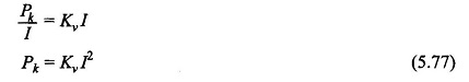
Pc = 3I2R, the copper-loss (factor 3 will not be present in a dc machine); R is the resistance parameter of the machine.
Pst = stray-load loss (copper + iron) = αI2
(Here the stray-load loss is assumed proportional to the square of the load current)
Pb = VbI = brush-contact loss (in dc machines); Vb being the brush-contact voltage drop
Hence![]()
Thus total DC Motor Losses can be expressed as a function of the current as
![]()
Generating machine:
Power output,
The maximum efficiency is obtained at (minimum denominator in Eq. (5.76))
Thus the maximum efficiency is reached at a load when the losses proportional to the square of current equal the constant losses. This is the same conclusion as arrived at for a transformer (Eq. (3.55)).
Motoring machine:

This also reaches the maximum value when
![]()
i.e. Constant losses = losses proportional to the square of current
As per the condition of Eq. (5.77) or (5.79) for maximum efficiency, the constant losses and variable losses (proportionality constant Kv) are so proportioned by the choice of machine dimensions as to yield maximum efficiency near about the full-load. The constant losses are mainly determined by the choice of flux density and the volume of iron used and the variable losses are governed by the choice of current density and the volume of copper used. Further, the flux density used is limited to slightly saturated values and the current density is limited by the allowable temperature rise (depending upon the class of insulation). Therefore, adjusting the machine efficiency to yield the maximum value at a particular load is an exercise in proportioning iron and copper to be used in the machine.
Maximum Output:
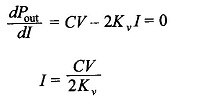
Consider for example the motoring machine. The power output is expressed as
![]()
It is a fairly good assumption to neglect Vb; in fact this term is not present in ac machines. Then
![]()
For maximum power output
The maximum power output is then given by
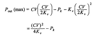
The power input is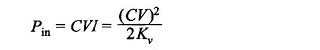
The efficiency at maximum power output is given by
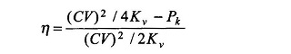
Obviously this will be slightly less than 50%. This is too low a value to be acceptable for a power-delivering device. Further, under maximum output operation, the losses being almost half the input, it would be impossible to limit the temperature rise to the allowable value. Thus the electromechanical power devices are never operated to deliver maximum output. In fact these are operated at a load (nearly full-load) at which the efficiency is maximum. This is in contrast to electronic devices (low power) which are usually operated to deliver maximum power output as the total power being very small, the efficiency is of secondary consideration. Further, the problem of heat (caused by losses) dissipation is not so intense as in large power DC Motor Losses and Efficiency.