HVDC Circuit Breakers – Construction and Working Principle:
Light duty dc circuit breakers have been in use since long. However, there is lack of suitable circuit breakers for HVDC systems. At present most of the HVDC systems are with two terminals and in a two terminal HVDC system, HVDC circuit breakers are not required because fault current can be controlled or eliminated by controlling the firing angle of the converters. In multi-terminal HVDC systems, the need of HVDC circuit breakers will arise.
Problems of Direct Current Interruption:
AC circuit breaker easily interrupts the arc at natural current zero in the ac wave. At current zero, the energy (1/2 Li2) to be interrupted is also zero. The contact gap has to cool and recover the dielectric strength to withstand natural transient recovery voltage. With dc circuit breakers, the problem is more complex as the dc waveform does not have natural current zeros. Forced arc interruption would produce high transient recovery voltage and restrike without arc interruption and ultimate destruction of the breaker contacts.
In designing of HVDC circuit breakers, there are three main problems to be overcome. These are (i) creation of artificial current zero (ii) prevention of restrikes and (iii) dissipation of stored energy.
Working Principle:
The artificial current zero principle is used in HVDC circuit breakers for arc quenching. By introducing a parallel L-C circuit, the arc currents are subjected to oscillations. These oscillations are severe and have several artificial current zeros. The breaker extinguishes the arc at one of the artificial current zeros. The crest currents of the oscillation must be greater than the direct current to be interrupted. Figure 8.20 shows the schematic diagram of such a scheme.
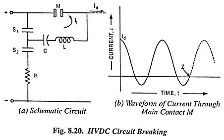
A series resonant circuit with L and C is connected across the main contact M of a conventional ac circuit breaker through an auxiliary contact S1 and resistor R is connected through contact S2. Under normal operating conditions, main contact M and charging contact S2 remain closed and the capacitor C is charged to line voltage through the high resistance R. Contact S1 is open and has line voltage across it. For interrupting main circuit current Id, the operating mechanism opens contact S2 and closes contact S1. This initiates discharge of capacitor C through inductance L, main contact M and auxiliary contact S1 setting up an oscillatory current shown in Fig. 8.20 (b). Thus artificial current zeros are created and the circuit breaker main contact M is opened at a current zero Z. Thereafter, contact S1 is opened and contact S2 is closed.
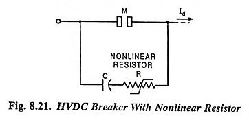
Another way of interrupting main circuit direct current is by its diversion to the capacitor so that the magnitude of current to be interrupted by the circuit breaker becomes smaller. This is illustrated in Fig. 8.21. The capacitor C is initially uncharged. When the main contact M opens, the main circuit current is diverted to the capacitor C. Thus the current to be interrupted by the main contact M becomes smaller. The rate of rise of the recovery voltage across M is dVc/dt = Id/C. The nonlinear resistor R absorbs energy without greatly adding to the voltage across the main contact M.
The problem of prevention of restrikes is more acute in oscillating current dc circuit breakers, where the time in which the current is chopped is very small (of the order 100 μs). Thus a steep surge of restriking voltage across the breaker terminals is produced and the circuit breaker must be capable of withstanding this voltage.
For producing a good deionizing arc, the space between two walls of arc chute can be narrowed for restricting the arc and simultaneously it may be splitted into a number of smaller arcs by inserting a grating of vertical metal plates.
A large amount of energy stored in the circuit inductance at the start of the interruption and that supplied by the rectifier during the interruption duration has to be dissipated, otherwise it will be transferred to the system capacitance and set up overvoltages. A protective spark gap may be connected across the circuit breaker so as to reduce the commutating capacitor size. It will also keep the abnormal voltage caused at the switching instant at desired level. By means of high frequency currents the spark gap acts as an energy dissipating device. Alternatively a Zno arrester may be connected across the breaker which will limit the transient recovery voltage and absorb associated energy.