Hunting in Synchronous Machine:
So far the operation of the synchronous machine under steady-state conditions at constant (synchronous) speed has been considered. Under these conditions of Hunting in Synchronous Machine
![]()
where
- Pe= electrical power output of the machine
- Pm= mechanical power input to the machine
the machine losses having been assumed negligible. These power flows are indicated in Fig. 8.65. If this power balance is disturbed, say for example, the mechanical power input slightly increases, the machine undergoes electromechanical dynamics wherein
Pm – Pe= Pa = accelerating power
Power Flow Diagram of Synchronous Motor:
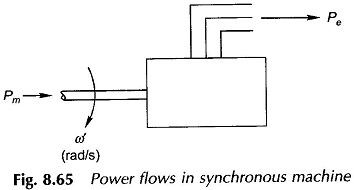
In the absence of losses this power is absorbed in accelerating the rotor inertia, i.e.
![]()
where
- I = moment of inertia of rotor in kg m2
- α′ = rotor acceleration in rad (meth)/s2
If powers are expressed in MW, Eq. (8.87) can be written as
M= inertia constant in MJ s/elect. deg; Pm, Pe are in MW
It is convenient to measure the rotor angle with respect to a synchronously rotating reference frame.
Let
![]()
where
- ωs = synchronous speed in elect. deg/s
- δ = rotor angular displacement from the synchronously rotating reference frame; this in fact is the angle by which Ef leads Vt
Taking the second derivative of Eq. (8.94),
![]()
Equation (8.92) therefore takes the form
It has already been shown that Pe is governed by the power angle characteristics of synchronous machine, i.e.
It is a nonlinear second order differential equation known as the swing equation.
Let the machine be operating under steady conditions of
![]()
With the mechanical input power remaining constant at Pmo, let the angle δ be distributed from δ0 to δ0 + Δδ. Then


Substituting in Eq. (8.98)
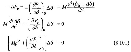
The incremental change Δδ = δ – δ0 is governed by the linear second order differential equation (8.101) whose characteristic roots are
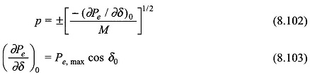
From Eq. (8.101), (∂Pe/∂δ)0 > 0 for δ < 90∘, i.e. in the stable operating zone of the machine, the roots of the characteristic equation (8.101) are a complex conjugate pair indicating sinusoidal oscillatory behavior about the operating point (Pe0, δ0).
Oscillatory behavior of the synchronous machine about the operating point has its origin in machine stiffness (or the synchronous link between rotor and stator fields which has a spring-type action). This oscillatory behavior known as Hunting in Synchronous Machine is highly undesirable—the electrical power fed to the mains and shaft torque oscillate, which in turn causes shaft fatigue. To minimize Hunting in Synchronous Machine to a tolerable level the oscillations must be damped out by introducing a damping term (proportional to dδ/dt) in the swing equation (Eq. (8.98)). In fact a small amount of damping, contributed by system losses (both mechanical and electrical), is always present in the machine but this is insufficient to kill hunting. Additional damping must therefore be introduced in the machine.
Damper Winding for Salient Pole Machine:
Additional damping is provided in the salient pole synchronous machine by means of damper bars located in the main poles of the machine and short-circuited through round rings at both ends as shown in Fig. 8.66. As the rotor oscillates, the damper bars have a relative movement with respect to the air gap flux pattern which causes induction of emfs and flow of currents in these bars. The torque created by the bar currents as per Lenz’s law always opposes the relative motion.
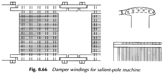
This is how a positive damping term is brought into play so that the oscillatory motion of the rotor about the operating point is considerably reduced in amplitude and the rotor quickly returns to the steady position. These short-circuited bars are known as damper winding or ammortisseur winding. These act like the squirrel cage of an induction motor thereby providing a starting torque for the motor which otherwise being of synchronous kind is non-self-starting. Therefore, the damper winding serves the dual purpose.
Synduction Motor:
A synduction motor started on the induction principle by means of damper winding is known as the synduction motor.
On starting, the rotor achieves a speed close to synchronous and the rotor and stator fields lock into each other as soon as the field excitation is switched on.