Measuring Instruments in Electronic Instrumentation Articles:
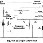
Output Power Meter Working Principle: The Output Power Meter Working Principle is designed to directly measure the output power in an arbitrary load. The instrument provides a set of resistive loads to be selected for power measurements. In addition to power, … (Read More)
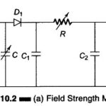
Field Strength Meter (Transistor) Circuit: The Field Strength Meter is used to measure the radiation intensity from a transmitting antenna at a given location. With its own small antenna, it is essentially a simple receiver with an indicator. The wavemeter circuit with … (Read More)
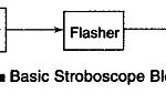 Stroboscope Working Principle: The stroboscope working principle uses a high intensity light which flashes at precise intervals. This light may be directed upon a rotating or vibrating object. The stroboscopic effect is apparent when the rotational or vibratory speed is in … (Read More)
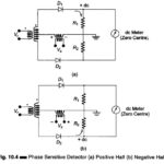
What is Phase Sensitive Detector or Phase Meter Circuit?: Figure 10.4 shows a Phase Sensitive Detector or Phase Meter Circuit for comparing an ac, signal with a reference signal. The Phase Sensitive Detector Circuit produces a rectified output, which is fed to … (Read More)
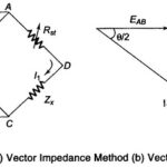
Vector Impedance Meter (Direct Reading): If some knowledge of the reactive and resistive factors is needed, in addition to obtaining a direct reading of the magnitude of the impedance (Z), a test method for determining the Vector Impedance Meter may be employed. This … (Read More)
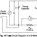
Q Meter: The overall efficiency of coils and capacitors intended for RF applications is best evaluated using the Q value. The Q Meter is used to measure some electrical properties of coils and capacitors. The Q Meter Working Principle is based … (Read More)

LCR Bridge: Basic LCR Bridge (Skeleton Type) : A simple bridge for the measurement of resistance, capacitance and inductance may be constructed with four resistance decades in one arm, and binding post terminals to which external resistors or capacitors may be … (Read More)
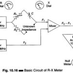
RX Meter Circuit in Measuring Instruments: An RX Meter Circuit in Measuring Instruments is used to measure the separate resistive and reactive components of a parallel Z network. It is especially useful in the design of RF tank circuits but can … (Read More)
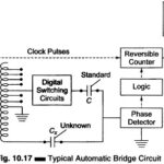
Automatic Bridge Circuit: The bridges discussed so far require that the controls be adjusted for balance after each capacitor (or other devices being tested) is connected to the bridge. In effect, they are manual. In recent years a number of automatic … (Read More)
Transistor Tester and its characteristics: The term Transistor Tester (or analyser) used in this text is for instruments giving quantative measurements of transistor parameters. The tester should be able to provide direct readings for at least two important measurements, such as: A … (Read More)
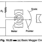
Megger Circuit Diagram: Another common method of measuring resistances above 50 M Ω is the Megger Circuit Diagram (megaohmmeter) shown in Fig. 10.23(a). This instrument is used to measure very high resistances, such as those found in cable insulations, between motor … (Read More)
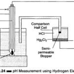
pH Measurement Methods: pH is defined as the negative logarithm of the active hydrogen ion. It is a measure of the acidity or alkalinity of an aqueous solution. The pH scale runs from 0 – 14, with pH 7, the neutral … (Read More)