BCD Adder Circuit | BCD Adder Truth Table | BCD Adder Block Diagram:
The digital systems handles the decimal number in the form of binary coded decimal numbers (BCD). A BCD Adder Circuit that adds two BCD digits and produces a sum digit also in BCD. BCD numbers use 10 digits, 0 to 9 which are represented in the binary form 0 0 0 0 to 1 0 0 1, i.e. each BCD digit is represented as a 4-bit binary number. When we write BCD number say 526, it can be represented as

Here, we should note that BCD cannot be greater than 9.
The addition of two BCD numbers can be best understood by considering the three cases that occur when two BCD digits are added.
Sum Equals 9 or less with carry 0
Let us consider additions of 3 and 6 in BCD.

The addition is carried out as in normal binary addition and the sum is 1 0 0 1, which is BCD code for 9.
Sum greater than 9 with carry 0
Let us consider addition of 6 and 8 in BCD
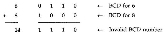
The sum 1 1 1 0 is an invalid BCD number. This has occurred because the sum of the two digits exceeds 9. Whenever this occurs the sum has to be corrected by the addition of six (0110) in the invalid BCD number, as shown below

After addition of 6 carry is produced into the second decimal position.
Sum equals 9 or less with carry 1
Let us consider addition of 8 and 9 in BCD

In this, case, result (0001 0001) is valid BCD number, but it is incorrect. To get the correct BCD result correction factor of 6 has to be added to the least significant digit sum, as shown below

Going through these three cases of BCD addition we can summarise the BCD addition procedure as follows :
- Add two BCD numbers using ordinay binary addition.
- If four-bit sum is equal to or less than 9, no correction is needed. The sum is in proper BCD form.
- If the four-bit sum is greater than 9 or if a carry is generated from the four-bit sum, the sum is invalid.
- To correct the invalid sum, add 01102 to the four-bit sum. If a carry results from this addition, add it to the next higher-order BCD digit.
Thus to implement BCD Adder Circuit we require :
- 4-bit binary adder for initial addition
- Logic circuit to detect sum greater than 9 and
- One more 4-bit adder to add 01102 in the sum if sum is greater than 9 or carry is 1.
The logic circuit to detect sum greater than 9 can be determined by simplifying the boolean expression of given BCD Adder Truth Table.


![]()
With this design information we can draw the BCD Adder Block Diagram, as shown in the Fig. 3.32.

As shown in the Fig. 3.32 , the two BCD numbers, together with input carry, are first added in the top 4-bit binary adder to produce a binary sum. When the output carry is equal to zero (i.e. when sum ≤ 9 and Cout = 0) nothing (zero) is added to the binary sum. When it is equal to one (i.e. when sum > 9 or Cout = 1), binary 0110 is added to the binary sum through the bottom 4-bit binary adder. The output carry generated from the bottom binary adder can be ignored, since it supplies information already available at the output-carry terminal.